


Note that we are writing this complete story (all 7 parts), (mostly) after we have already made the entire new center console.
Now that it’s finished, as always, with articles of this type of in-depth and multi-step processes, we didn’t want any single story to be too long.
Hence the breaking the entire thing down into numerous posts.
It makes it much easier to digest everything that way, and you don’t get lost within the story!
Tomorrow’s post (the actual build) was just going to be way too long, and we noticed a bunch of little things/parts that need to be created for the console, so we decided to make todays post about the prep work, and the producing of all these parts that need to be attached to the console.
There is a lot of putting the console in and out of the car as the build progresses to check certain things.
It can’t be totally built within the car as the seats are in the way, and the console needs to be flipped upside down sometimes.
Luckily for you, we’re minimizing that, should you be following along to create your own console.
Pre-making the parts as shown below will aid in the build and in/out of car steps needed.
.

.
This is an ongoing series about creating a new custom center console unit for a Buick Grand National.
See the steps taken below to create (will be linked after publication).
This is day 4 of 7 – you’re half way thru this series! The best is yet to come!
.
Find the first part (thoughts, plans) here:
Custom Center Console for Buick Grand National (1 of 7)
Find the second part (specs, parts, building template mockup) here:
Custom Center Console for Buick Grand National (2 of 7)
Find the third part (wood size choices & the weight differences) here:
Custom Center Console Buick Grand National (3 of 7)
Find the fourth part (prep work, cut out parts) here:
Custom Center Console Buick Grand National (4 of 7)
Find the fifth part (building the console) here:
Custom Center Console for Buick Grand National (5 of 7)
Find the sixth part (wiring up all the lights) here:
Custom Center Console for Buick Grand National (6 of 7)
Find the seventh part (installing the console) here:
Custom Center Console for Buick Grand National (7 of 7)
.
TOOLS:
– cordless drill (with phillips bit & 1/8″ + 3/8″ drill bit)
– saw for cutting MDF sheet
– 1 1/4″ & 2 1/4″ holesaw (for gauges & usb / power port)
– 4″ holesaw (for tri shield emblems on the sides)
– nail / staple gun
– 7mm socket (removing/installing 2 bolts holding console into place)
– wire crimps
[note: you should predrill all screw holes so the 1/2″ MDF doesn’t crack!]
.
When we did the usb charger mod to replace the OEM cigarette lighter, which was a very useful modification considering most accessories nowadays use a usb cord, we realized some time later that older items (like radar detectors, power inverters, etc.) do actually use the cigarette lighter (AKA power outlet) type plugs, so this style of plug could be beneficial to have when required.
We have an older style power inverter (and a tire inflator too) that does get used on very rare occasions, and utilizes this type of plug.
Luckily, we haven’t had the need to use either since we did that swap.
Making this new console however, gave us the opportunity to reinstall a plug end for use with a cigarette lighter type cord, for future use if it ever is needed.
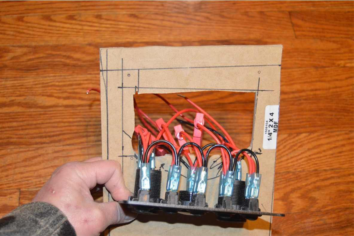
 We acquired a totally new switchplate for this build, which contains 5 switches, a power outlet plug, dual usb plug, and a volt gauge.
The volt display isn’t really needed since there’s already one in that original usb charger outlet we installed, so we don’t plan on even hooking this one up.
The new dual usb charger will be useful for our passengers benefit (for their phones or whatnot), considering we use the first set for our own phone (for charging & map reading use) plus an ipod (tunes are important!).
The 5 new switches will replace the 4 existing ones that are in the ashtray switch panel now.
.
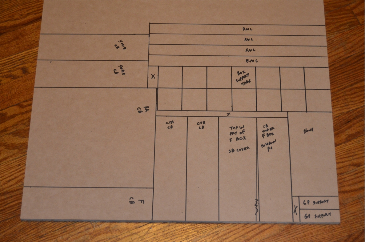
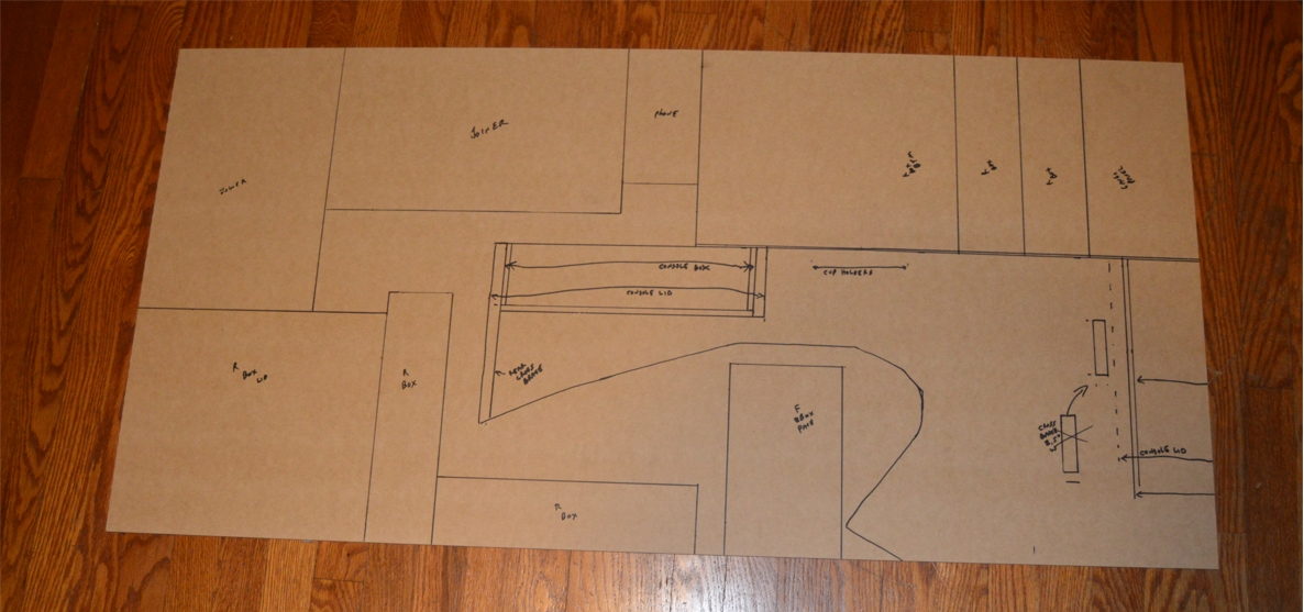
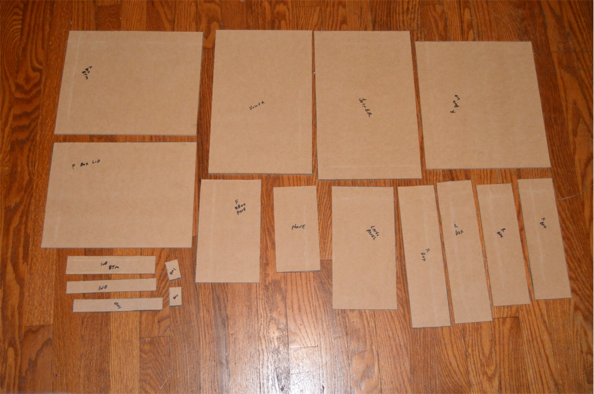
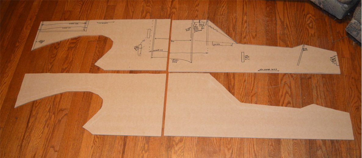
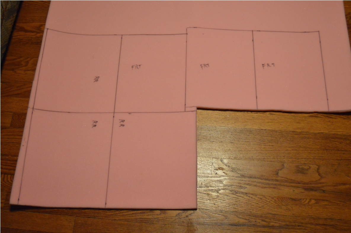
We literally drew out all of the pieces we needed onto the mdf sheets, then cut them all out.
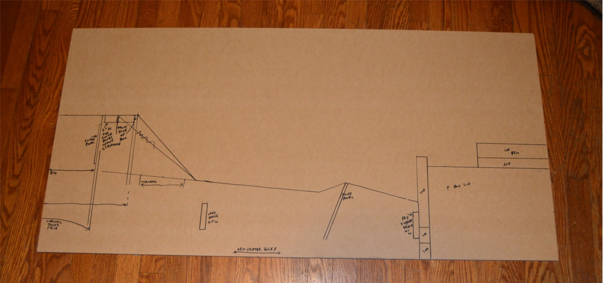
(we also spec’d out and drew ON the sidewall pieces where all of the components would fit in on it, so we could visually “see” where everything would sit once done)
.
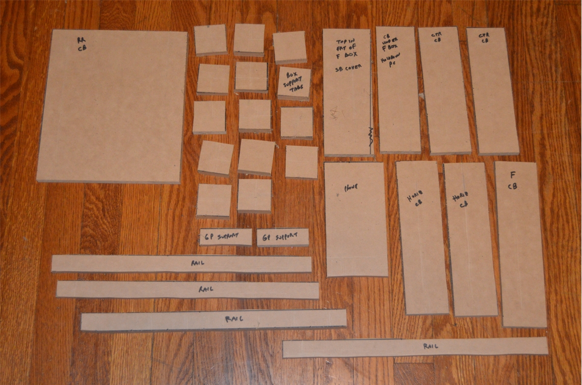
These are all the 1/2″ pieces we used:
.
.
These are all the 1/4″ pieces we used:
.
.
We will give you the list of pieces needed first, then explain what they are all for:
.
1/4″ MDF pieces needed:
(2) 14×36 & (2) 14×32.25 (for the sides of console)
(2) 8.5×14 (joiner pieces)
11.5×3 (rear box sidewall add-on)
8.5×9 (front box face)
(3) 8.5×11 (front box: front, rear, driver side)
8.5×9 (front box: bottom)
12 x 9 (front box: lid)
(2) 9×3 (rear box: front, rear)
12×3 (rear box: driver side)
12×10 (rear box: bottom)
10.5 x 12 (rear box: lid)
10×5 (gauge panel)
3.5×7 (phone box)
8.5-9.5 x 16.75 (shifter plate; size varies because of narrowed area)
8.25-9.75 x 15.50 (rear top plate; size varies because of narrowed area)
.
1/2″ MDF pieces needed:
8.5×11 (front box: passenger side)
12×3 (rear box: passenger side)
3.5×7 (phone box)
8.5×3 (switch panel cover lid)
10×2.5 (front brace, also servers as front wall)
10×8.5 (rear brace, also servers as rear wall)
(2) 8.5×2.5 (vertical braces: front, middle; these go between the seats)
9.25×2.5 (horizontal brace: rear)
10 x 2.50 (horizontal brace: rear, also serves as rear box front support)
9.75 x 2.50 (gauge panel brace)
8 x 2.50 (hold down piece)
(2) 14.50 x 1 (front rails)
(2) 7 x 1 & (2) 2.50 x 1 (rear rails)
(8) 2 x 2 (front box tabs)
(2) 3 x 1 (rear box brace: rear)
(2) 3 x 1 (front face brace)
.
PREP WORK:
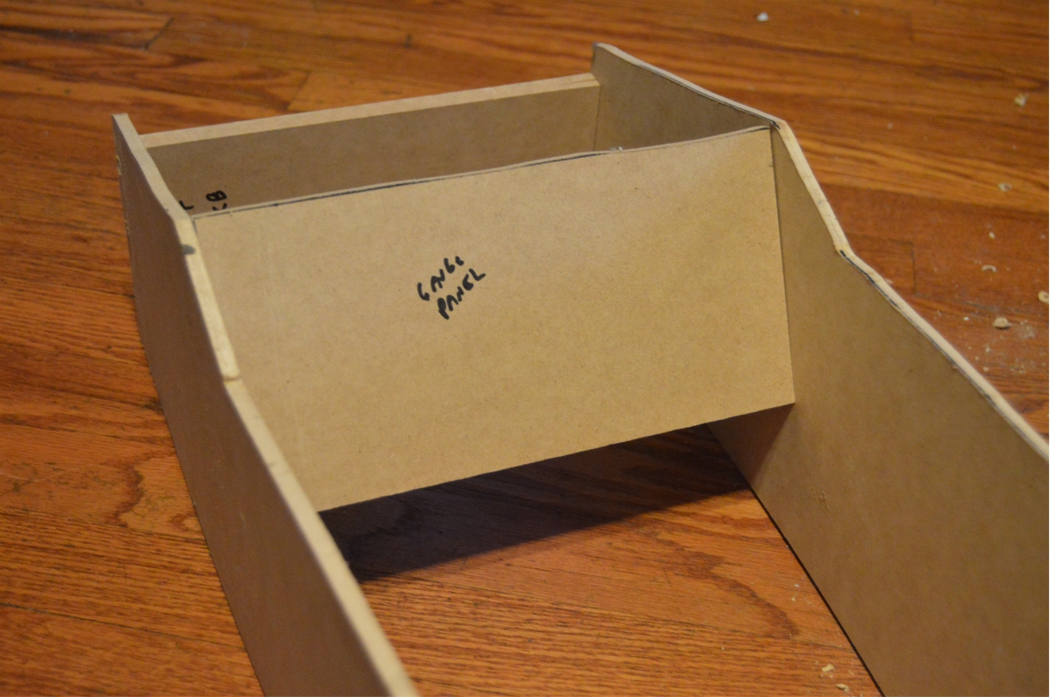
1. make 2 main vertical cross braces from MDF for the middle supports.
2. make 1 rear cross brace (which is also the rearmost wall of the console) from MDF, which fits the full height & width of the console.
It will be secured totally straight up and down on the rear of the console (vertically, which will make wrapping the console later with the vinyl much easier!).
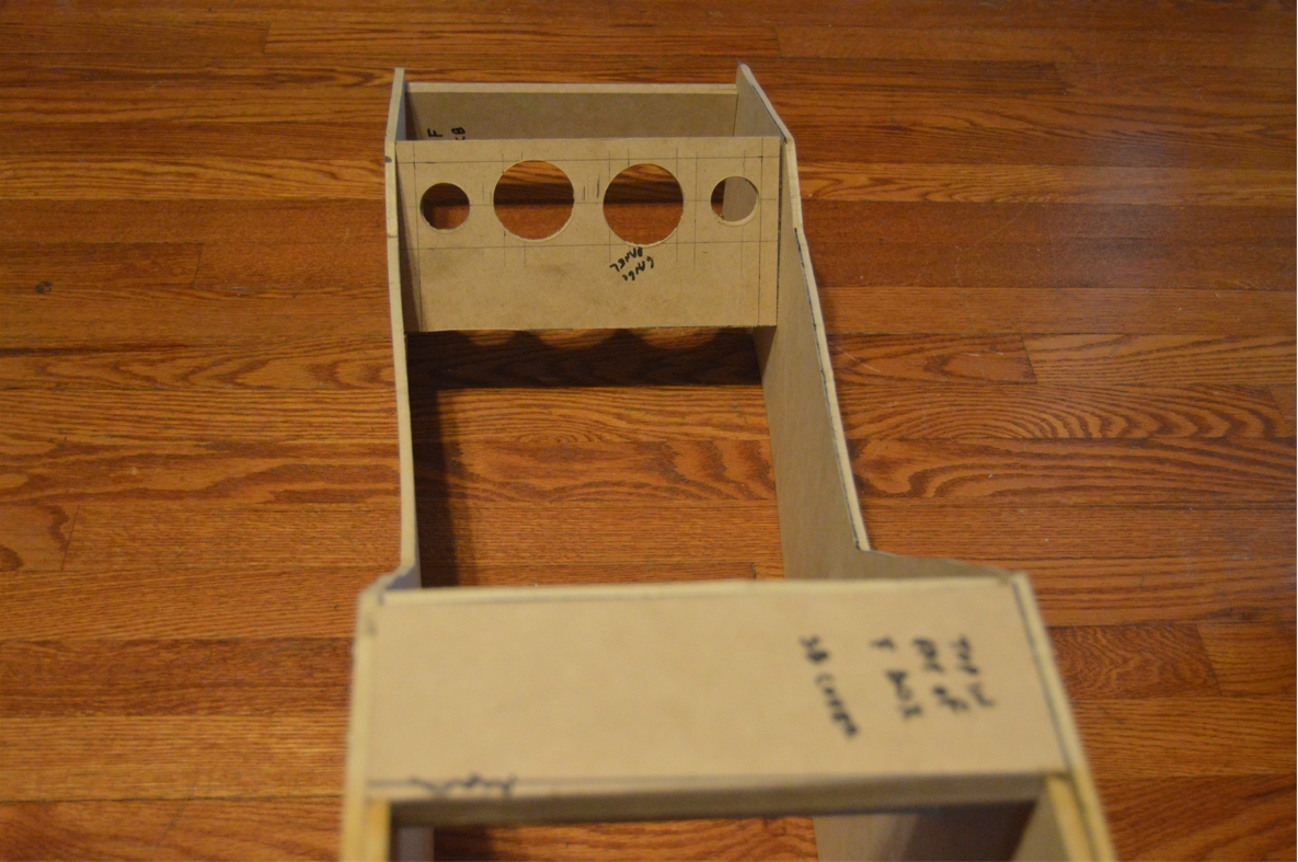
3. make front gauge holder panel.
We need 2 2.25″ holes for the 2 gauges we are putting in, as well as a 1.50″ hole for the shift light and a 1.25″ for the power port. These holes are centered (left to right) within this piece, and have an equal amount of distance between them (left to right).
The holes are 1/2″ from the top (we want some of this panel to hang down under where the main top piece will sit, to aid in supporting that piece).
2.25″ is remaining under the gauge holes at the bottom of the panel.
(the relays used in this build will be attached to the bottom of this panel, on the backside)
.
.
4. make gauge panel support.
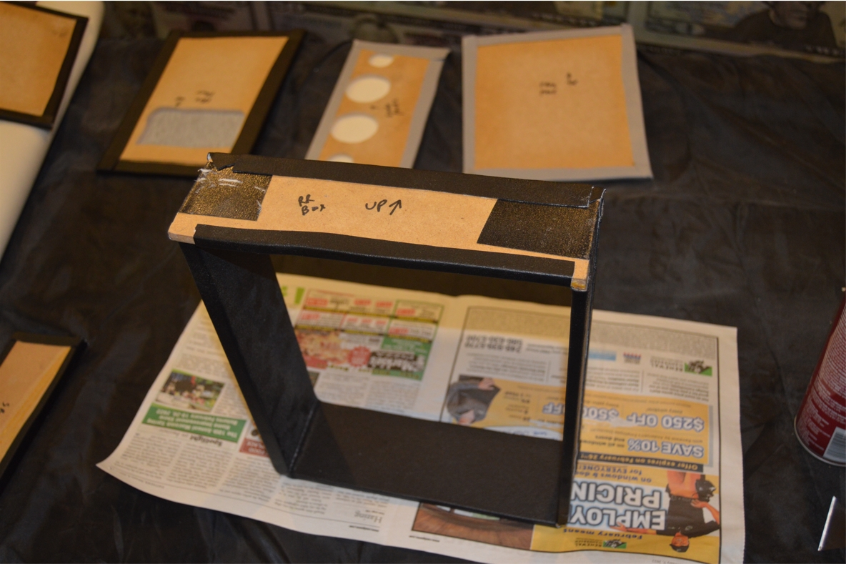
5. Make console boxes. Make 2 boxes like explained below.
2 boxes are made (1 for the front, 1 for the back).
the front box is: 8.25″ wide x 9″ long x 11″ deep.
the rear box is: 9.5″ wide x 12″ long x 3″ deep.
(these are outside dimensions, including the thickness of the mdf)
(the 1/2″ side pieces go on the PASSENGER side of the box, to support the hinge)
(the bottoms & the lids, are NOT included in the dimensions shown above)
The 4 sides of the box are secured together (we glued them), then wrapped on the INSIDE with black vinyl.
The bottom piece is made separately, then vinyl wrapped as well, and finally secured to the box.
(it’s done this way because it’s easier to wrap the vinyl around those 2 sections separately!)
[NOTE: we are using a switch plate on our console, set into the front console box, on the front side of the box, and the hole that was cut out for it, was done BEFORE we wrapped it with the vinyl]
.

.
6. make 8 small (2″ square) braces, 4 of them are attached to the outside of the front box, 2 on each side; 2 facing the front, 2 facing the rear, at the bottom of the box. These will be used to attach this box to the console. (the other 4 will be attached to the console sidewalls, in matching spots, and then they are all screwed to each other. This attaches the box to the console, and keeps the console sidewalls together as well from separating)
7. The rear console box gets a front full width brace, as well as 2 smaller pieces (1 on each side). This is how the rear box is attached to the console.
(The front brace provides support for the entire backside of the rear portion of the console box as well)
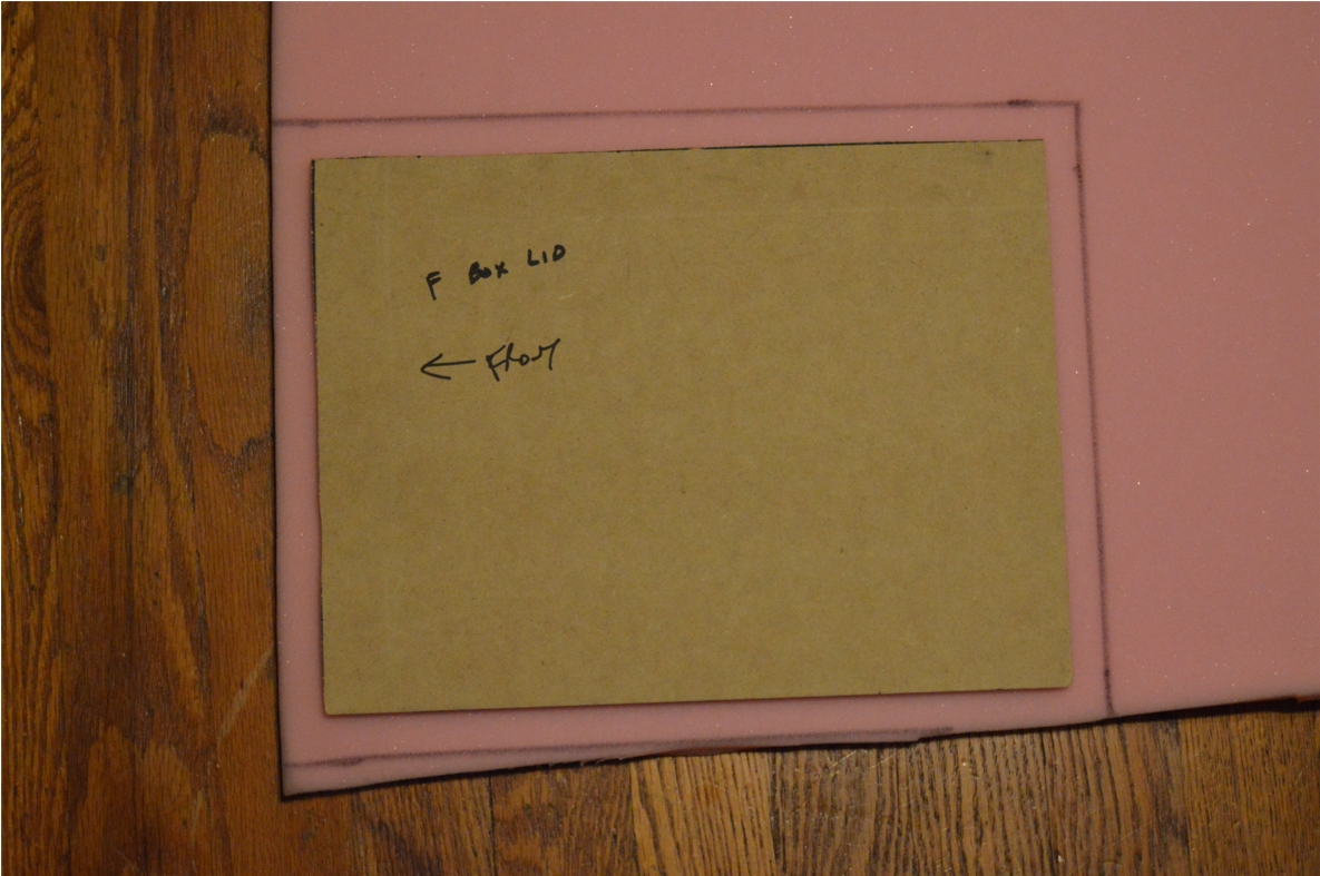
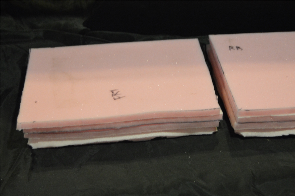
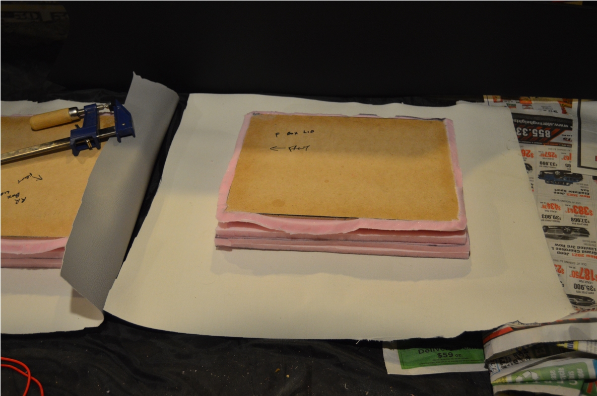
8. Make console box lids.
front: 9″ x 12″ – rear: 10.5″ x 12″
Pre-make where the hinges will be. Attach the hinges to the lid (predrill holes, mount hinges with screws, then remove all).
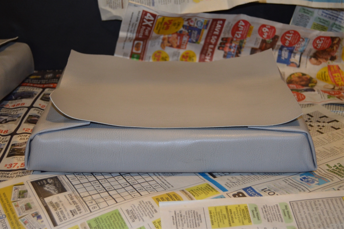
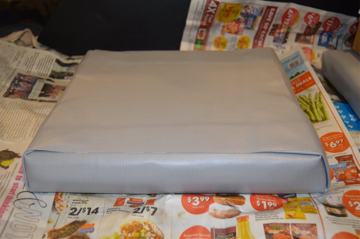
Spray the top sides and edges of the MDF with tack adhesive, let set up, then attach a piece of the foam (big enough to fill the top as well as wrap around the edges/sides of the MDF).
Spray the top side of the foam, let it setup, then set down another piece of foam (you don’t need to wrap the edges this time, just use a piece that goes all the way to the new edges created by the first layer of foam).
Do more layers like you just did. (creating a total of 4 layers of foam; 2″ tall)
[we did 4 layers (to make 2″ total thickness) because we are using 1/2″ thick foam padding]
[note: you could acquire thicker foam, but we bought this size because there are other areas of the console that require just 1 layer, so it made sense doing it this way. you could get 2 different sizes of foam if you prefer]
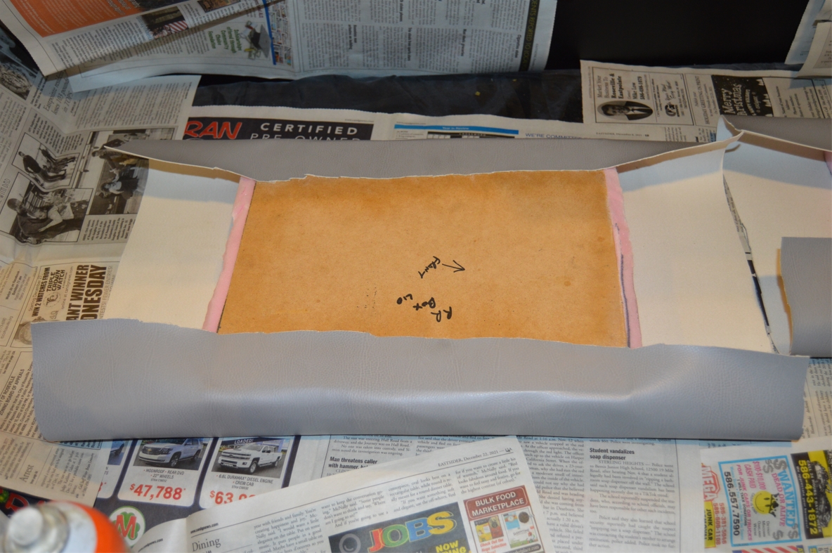
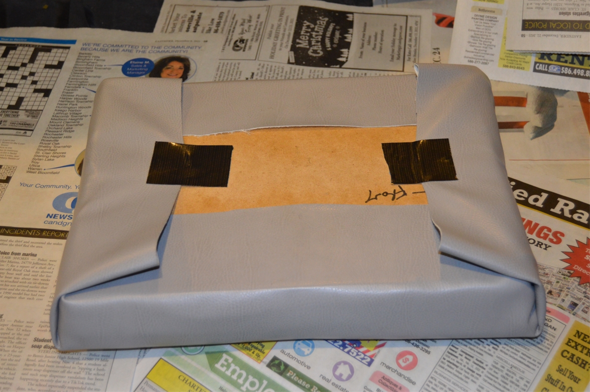
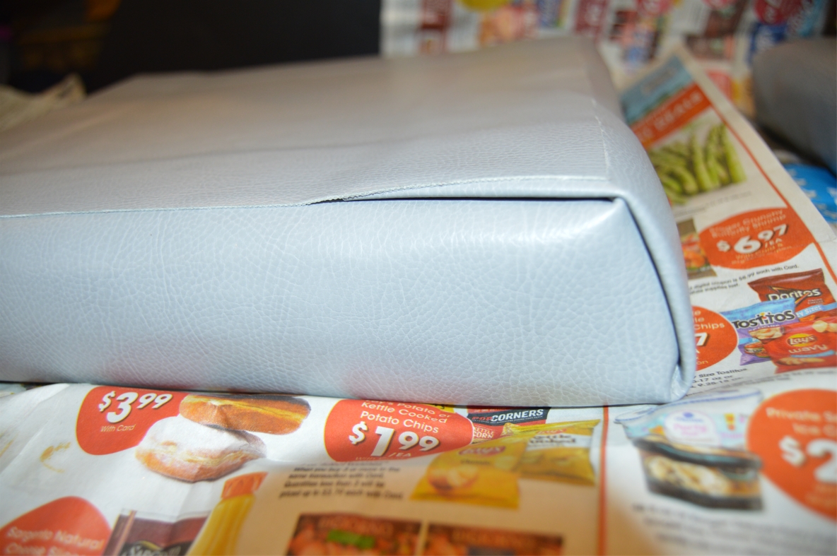
It’s pretty difficult wrapping the lids without (stitched) seams, while making it look “right” at the same time. We basically wrapped them like a Christmas present, folding the edges over, and securing them to the bottom of the lid. The (top side view) folded over corners are visually noticeable (unlike the other areas of this project), but look ok. After the main wrap was done, we glued another full size piece on the bottom of the lid to cover up the folded over edges (and to cover the center of the lid that had no vinyl on it), giving it a (mostly) finished appearance when the cover is lifted up off the console.
.


.
9. make front console underneath support brace. from the MDF. (main hold down piece)
10. make console box attachment braces. make 8 2″ square pieces from the 1/2″ MDF.
11. make console box front finishing panel. (front box face)
12. make 1 console box front finishing panel support brace. (switch panel cover lid).
13. make 2 shifter plate rail braces. These little support pieces will hold up the top plate in its proper position on the console.
14. make 2 pieces for the shifter plate.
(this is for our custom console, NOT needed if you intend on using the OEM plate)
(ON the shifter plate, for gear indicator hole, and phone holder. both mount underneath plate)
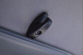
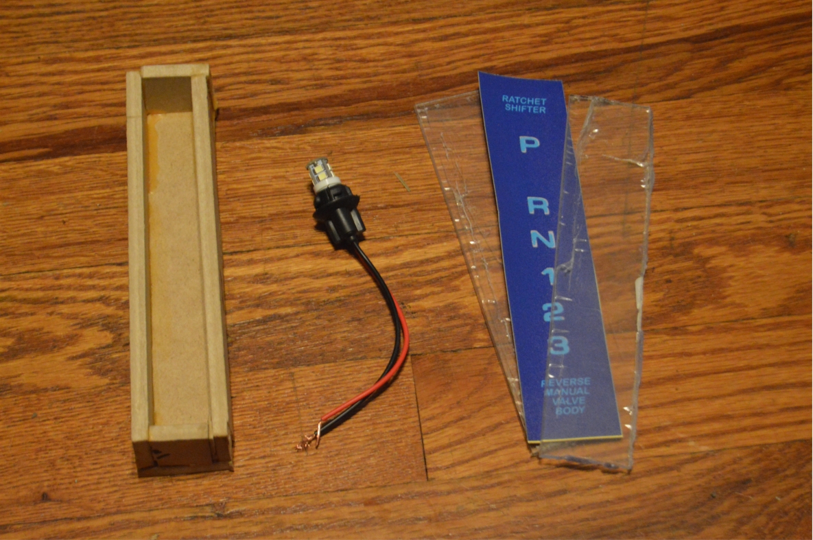
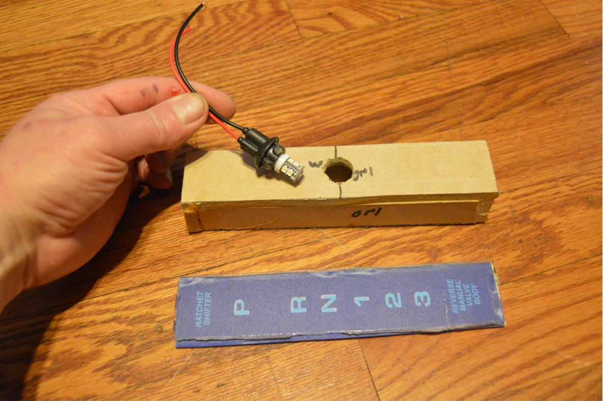
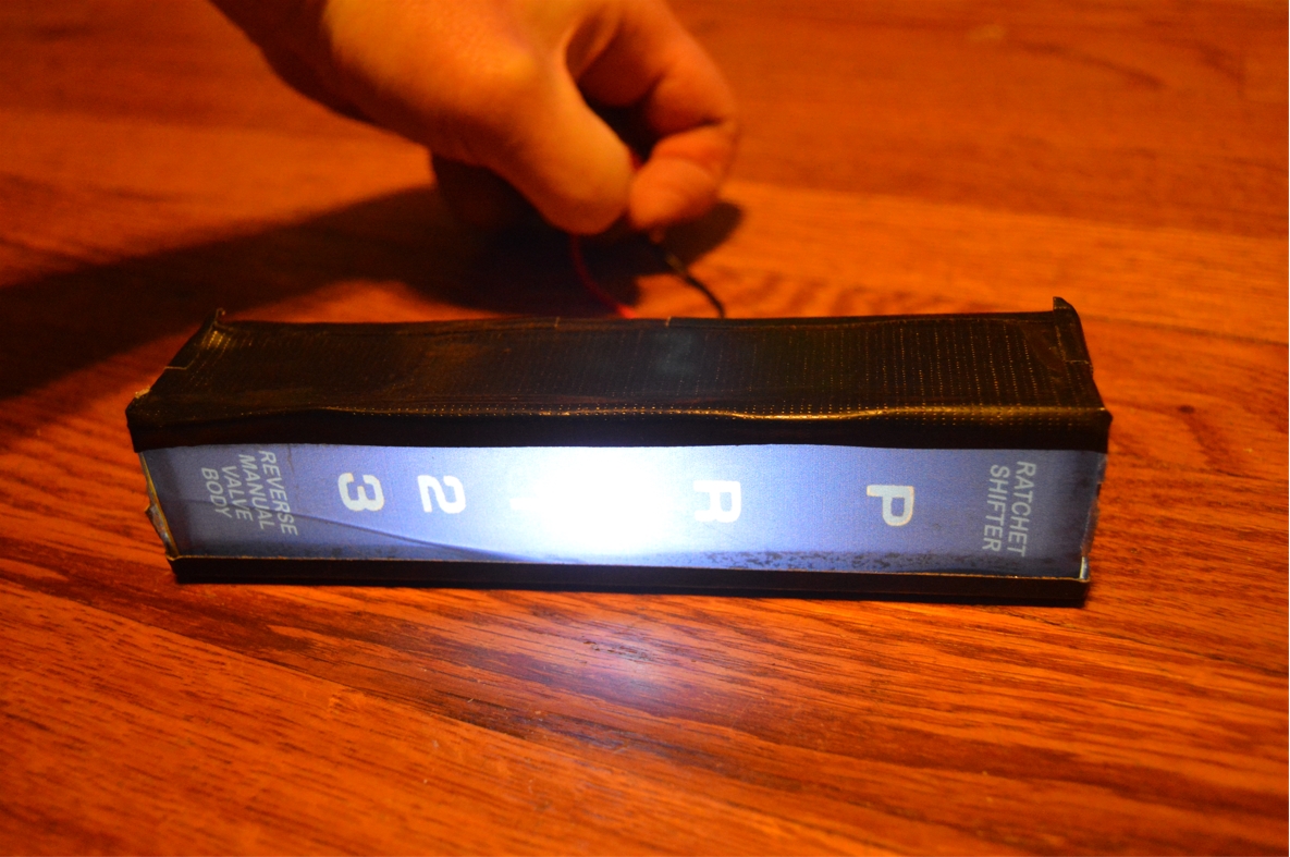
14A. The gear indicator: We had a decal made for this (1.5″ x 7″). We stuck it on a piece of (size matched) plexiglass. Then we made a box (1.5″ tall x 7″ long x 1.5″ wide) using the 1/4″ mdf. The plexi was set on the top. A bottom for the box was made, and a hole was drilled out so the factory indicator light/socket could be mounted inside it. The light does NOT indicate the separate gears like the factory version does, but it does shine through enough so all of the wording can be read on it. This assembly was attached to the new shifter plate. All pieces were connected to each other using the hot glue gun. It will be glued to the bottom of the new top plate. It also was duct taped into position.
.
.
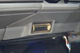
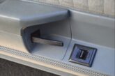
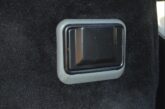
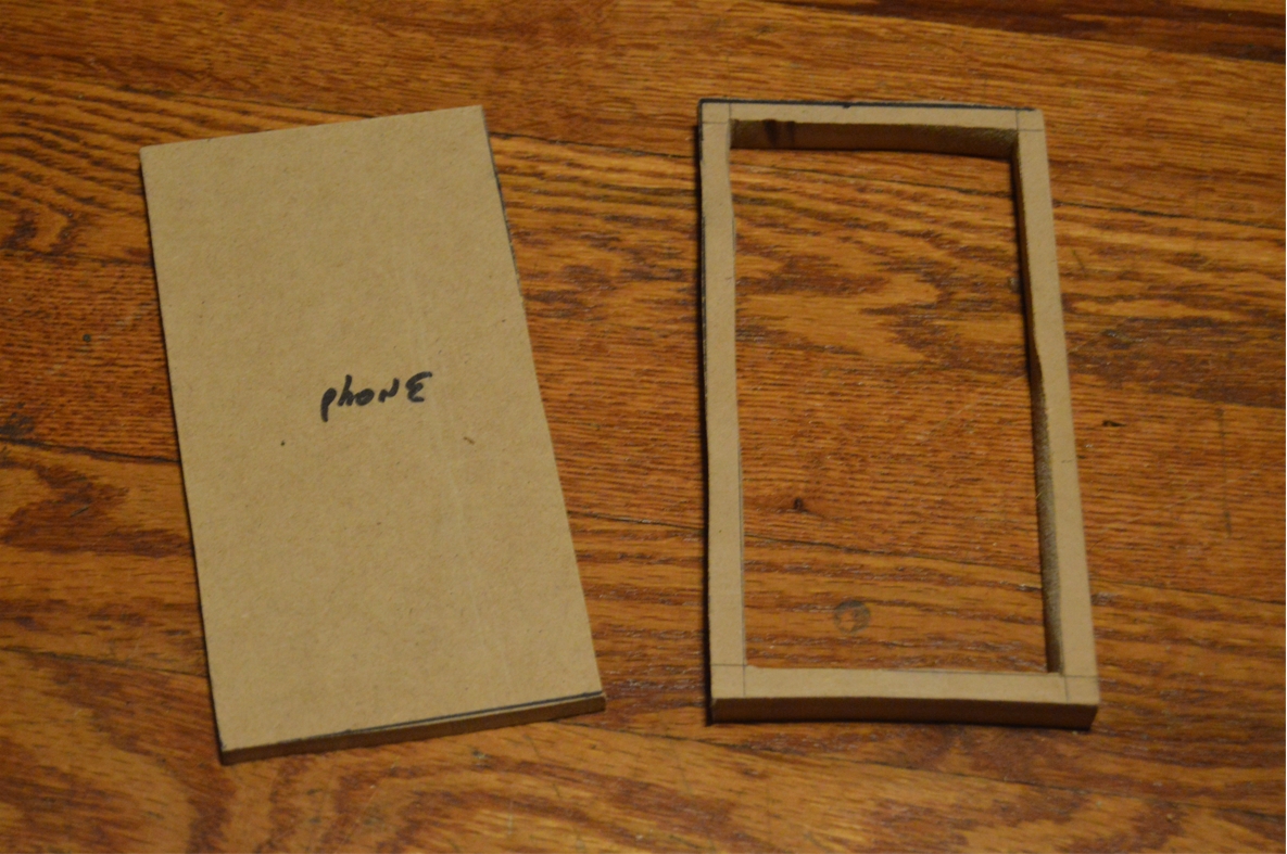
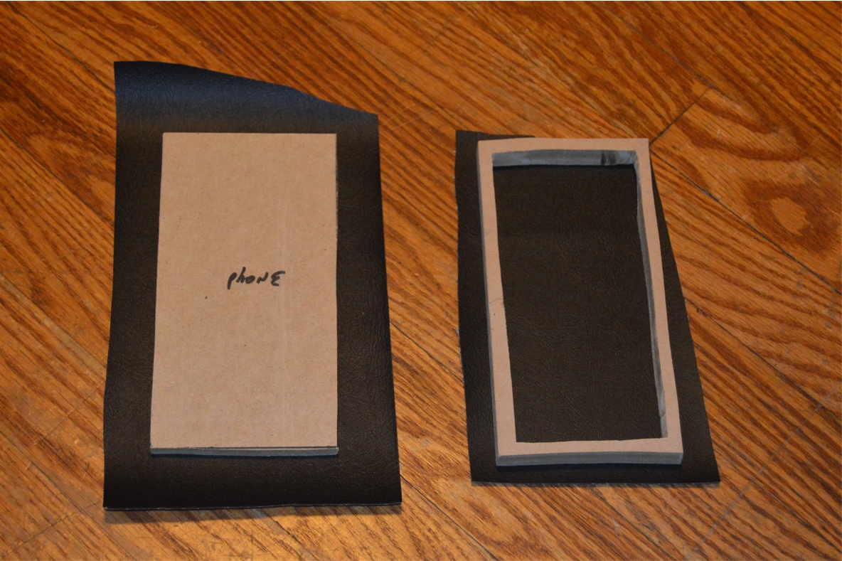
14B. The recessed phone holder: we made a piece using the 1/2″ MDF, then cut out a hole in the middle, leaving a 1/2″ border all the way around. This is an outer (upper) frame piece.
We made another same sized piece using the 1/4″ mdf. (this is the bottom piece).
We attached the 2 pieces together.
(this will create a nice drop-down, recessed panel, for this area)
It was wrapped with the black vinyl. It will be glued to the bottom of the new top plate.
.

.
15. make 2 rear plate rail braces.
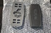
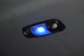
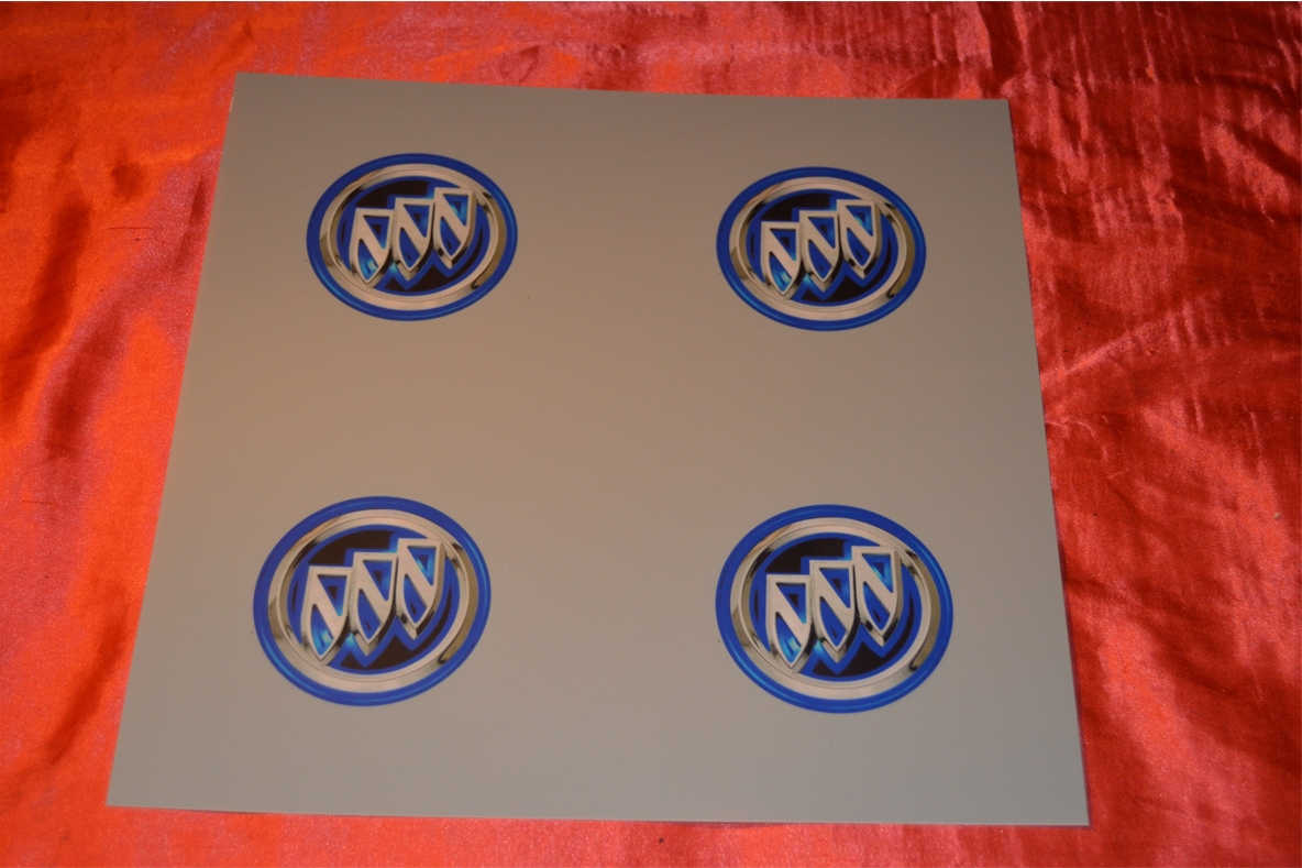
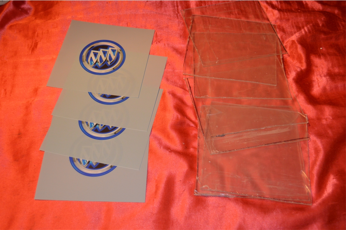
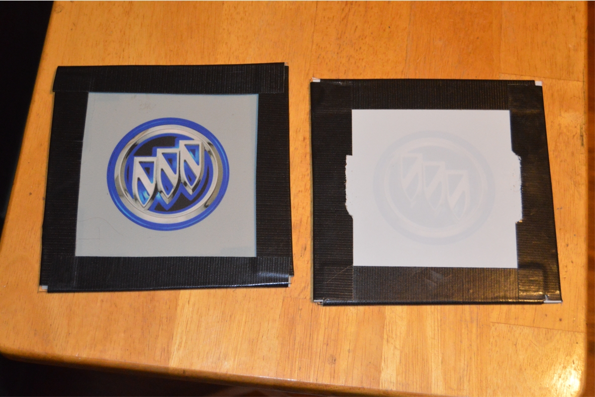
16. We are inserting some neat Buick Tri Shield logo pieces into the sides of the console.
a backlit decal was created and mounted on a matching sized 6″ square piece of plexiglass.
The actual image is 3″ round, and the holes on the sides of the console will be 4″ round.
These panels will be secured to the insides of the console sidewall.
.
.
The adventure continues tomorrow, stop by for the how-to on actually building the new center console!
.