With 25 year old wiring in your turbo regal, whenever you have the chance to upgrade to a hotwire kit (AKA direct power to a specific system via a relay type setup) you should take advantage of that!
It takes less strain off your original wiring system & gives you more power (or, the “correct” amount of power, AKA “proper voltage”) exactly where you need it!
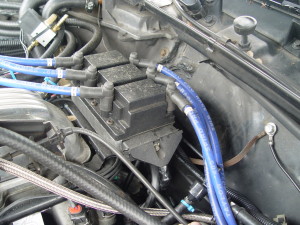
This do it yourself article will explain to you how to install a hot wire system to wire up your coil pack & ignition module.
Parts needed:
1- 30/40 amp relay.
1 ring terminal (to attach to alternator).
18 gauge wire (length depending, red in color).
14 gauge wire (length depending, red & black colors helpful).
shrink wrap or electrical tape.
small amount of wire loom.
assorted spade terminals (to join new 14/18 ga. wires to the relay & the connections at the IM). {or soldering all the wire connections works too}.
Time to finish: less than an hour.
.
.
How to do:
1. disconnect battery.
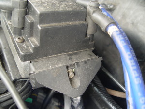
2. unbolt the main connector at the ignition module.
3. “unsnap” the connector to gain access to the wires.
you are going to have to cut 2 wires from this connector.
Leave yourself enough room on both sides of the wire to be able to make the new connections!
There’s not much room to work here, so THINK before you cut!
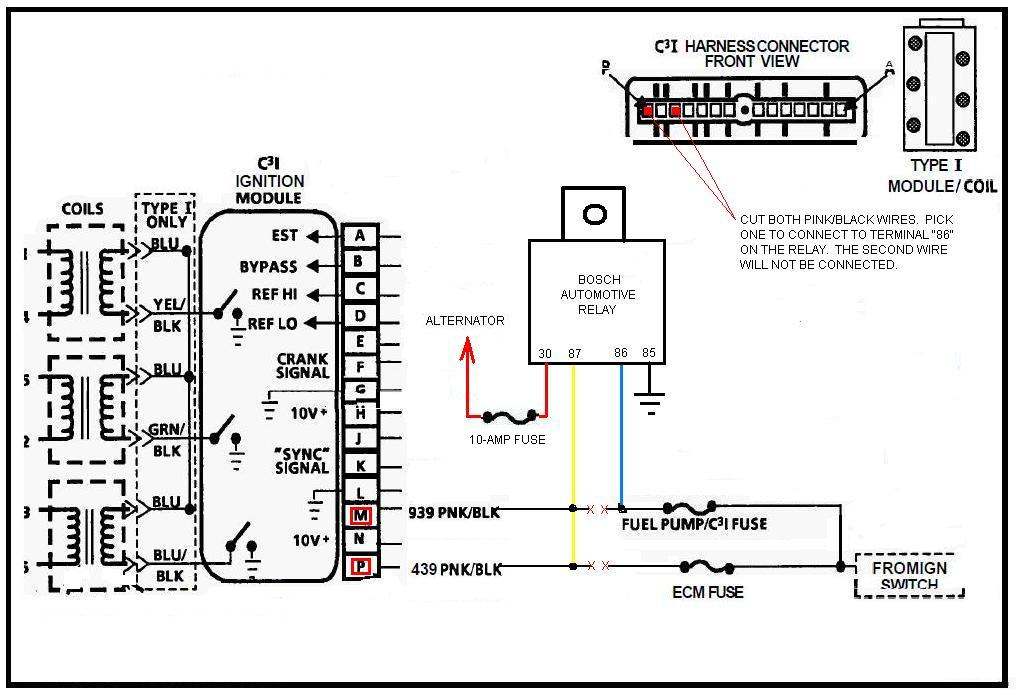
The wires to cut are the “M” & “P” wires:
The first is located at the far left {the last wire, “P”, closest to the front of the car when the connector is attached on the IM},
the second wire is the 3rd wire from the left {“M”}.
They are both a pink wire with a black stripe.
Try to place them together & cut them at the same length.
.
4. Join together the 2 wires you cut from the main connector (on the side that goes TO the ignition module) using a male spade connector.
Using some of the new 14 gauge wire (preferably red) attach a female spade connector to the end.
Attach these 2 connectors together.
shrink wrap or use electrical tape to seal the connection.
Depending on where you are going to mount the relay for this setup, determines the length of wire you will need.
(it might be convenient to just mount the relay on the firewall behind the coil pack.)
{figure out where exactly the relay will be mounted, so you know how much wire you will need to mount it there, but wait to actually secure it down until AFTER you’ve made all your wire connections. It’s easier that way!}
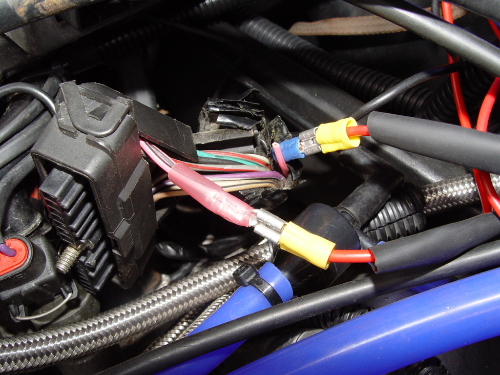
Now, take the other end of the 14 ga. red wire and attach it to the relay’s terminal #87.
This becomes the ignition modules new power source (feed line).
5. using a female spade connector, attach it to the other side of the wire you cut from the previous step (the pink with black stripe wire that goes TO the fusebox).
Choose ONE of the 2 wires you cut to attach this female connector to.
They both go to the fusebox, so it really doesn’t matter which one you choose.
{we chose the wire that was attached to terminal “M” because its the one marked CCCI (C3I) fuse in the fusebox, and it’s convenient for remembering that if you ever need a reference IN the fusebox in the future}.
Seal off the wire you didn’t choose with electrical tape, etc.
Using a male connector, attach it to the end of a new piece of 18 gauge red wire.
Connect the 2 new ends together (the new wire & the old pink/black wire).
Shrink wrap or tape it up.
Then attach the other end of the 18 gauge wire to terminal #86 on the relay.
{notice that we reversed the male/female connectors on both sides of the original pink/black wires. This was done purposely, so if in the future you need to disconnect these wires for any reason, there will be no confusion as to what gets connected back to which wire. (male connector attached TO the IM, female attached FROM the fusebox) – (also useful for putting it back to the way it was originally, if that need ever arises!)}.
6. Using another piece of red 14 gauge wire, attach a ring terminal to the end, then connect it to the back of the alternator.
Run this wire to the relay, and connect it to terminal #30.
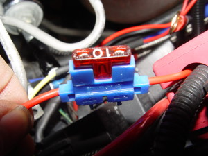
Now, you want THIS wire fused, so somewhere within this feed line, splice in a 10 amp fuse.
This wire becomes the new FEED wire, that supplies power to the relay (input, via terminal #30), which in turn, supplies power to the ignition module and coil pack (output, via terminal #87).
{BOTH of these wires, from step 4 & 6, are the new “hotwire” that actually powers up & runs the coil/IM}.
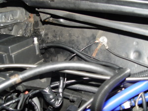
7. using a new black 14 ga. wire, connect it to a ground point, such as the engine ground point that is located on the firewall.
Connect the other end of the wire to terminal #85 on the relay.
{a good idea to do while you’re here: as an easy but redundant type of ground source, you should also make up another small piece of 14 gauge black wire & attach one end to the firewall ground point, and the other end to one of the studs from the ignition module bracket. Grounds are good! The more the better with these cars!}.
8. Make sure all of your connections are either shrink wrapped, or sealed up with electrical tape.
9. Mount the relay to the firewall (or wherever else you have decided).
10. Put the main connector back together & bolt it back up to the IM.
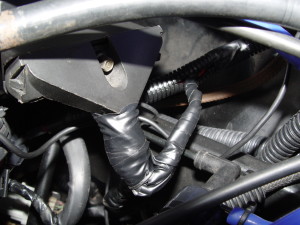
11. It might be a good idea to use electrical tape (etc.) to again rewrap all of the wires coming out of the IM connector.
Use wire loom if you have it, to cover up all of the exposed wires.
12. Reconnect battery.
13. That’s it!
Start your car up & make sure it runs!
If it does, you’re good!
If not, recheck your connections.
.
{instead of the 18 gauge wire, we just used all 14 gauge wire for this setup, which is fine. using all bigger wire is ok, but DO NOT use 18 ga. in place of the 14 ga., THAT is NOT ok!}
.
[when you turn the key forward (switched power), this energizes (“turns on”) the relay via terminal #86 (which was the old wire supplying power to the IM), along with using terminal #85 (a ground wire) to complete the (first half of the) circuit. When the relay is “energized” it allows terminal #30 (new incoming power) to get full voltage (from the alternator), and sends it out (new power feed) to the ignition module & coil pack via terminal #87 (hot wire)]
.


