


Serious Turbo Regal drag racers, those who have a need for something like this on the street (hehehe 😉 ), or those who want to make easy application of doing a burnout, should think about acquiring a line lock system for their Turbo Buick.
This item has a few different names, all doing the same job:
Line lock, roll control, stage control.
[but some systems are meant to “hold” the front brakes, others hold the rear, some do both]
Mainly used for holding the front brakes locked (and the rear brakes not being used temporarily) while you’re doing a burnout (so your rear wheels can spin freely – and you don’t abuse your rear brakes), and/or holding your G-body Regal on the starting line when you are staging your car at the racetrack (or elsewhere).
Either or both of these uses will let your Turbo Regal have less wear and tear, and also give you better control of your vehicle, when the time is right to use a product such as this.
There’s a few different “kits” available from numerous sources, but from the most common ones I looked at, none are totally “complete” with literally everything you need (meaning ALL parts to fully install), except for the one GNS sells.
You might be able to piece together your own fully equipped system, but why?
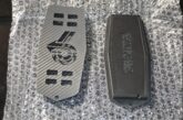
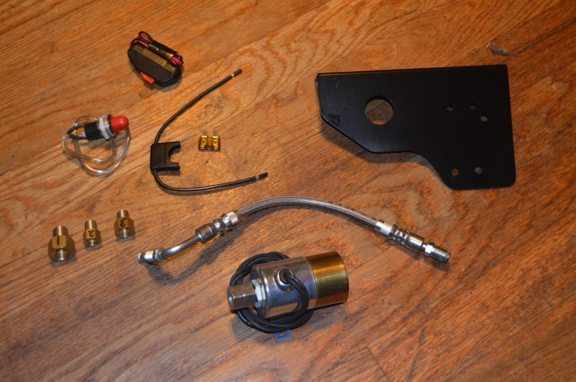
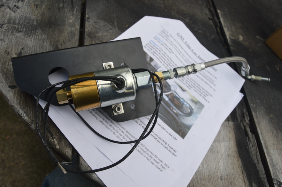
This kit comes with everything needed to complete your install, including the solenoid, GNS Line Lock mounting bracket, a switch kit and a new stainless steel braided line, along with the correct adapter fittings for the master cylinder and solenoid. Wiring and install instructions are included in the package.
.
.
You can get the kit by clicking below.

.
This addition is something we have been wanting for the 1987 Buick Grand National we’re working on.
Now that our install is complete, we are pretty happy with the GNS Line Lock kit and how everything turned out.
It works well and does what it’s suppose to do!
The kit is a bit pricey compared to others out there, however, you get a nice black painted bracket that the solenoid sits on (and is positioned exactly where it needs to be), plus an awesome (correctly sized on length) braided line that fits into the master cylinder and looks great too! You don’t have to worry about bending and working a regular brake line around to the solenoid. You won’t get these 2 items with other kits, so you’ll have to figure something else out. Not to mention the adapter fittings that are the right ones that work right out of the box.
.
It’s a fairly simple install. Unscrew the rear line from the master cylinder & screw it into the outlet of the solenoid, then take the new line & screw one end into the solenoid, the other into the master cylinder. There’s a total of 3 brass adapter fittings that are used in between the lines. Then you just wire it up & you’re good to go!
.
The kit includes a switch, an inline fuse (with 5A fuse), and a red “in use” light.
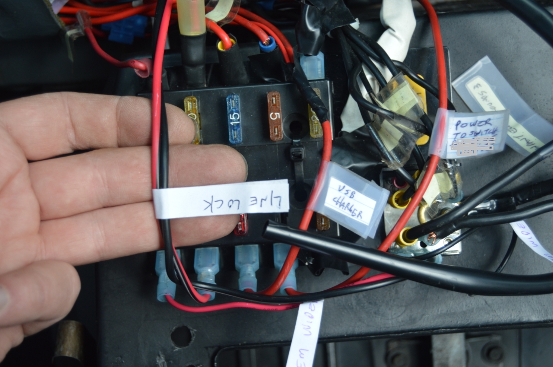
We aren’t using any of that since we are hooking it up thru the second fusebox that this ’87 Buick GN has.
It will still use a 5 amp fuse for power.
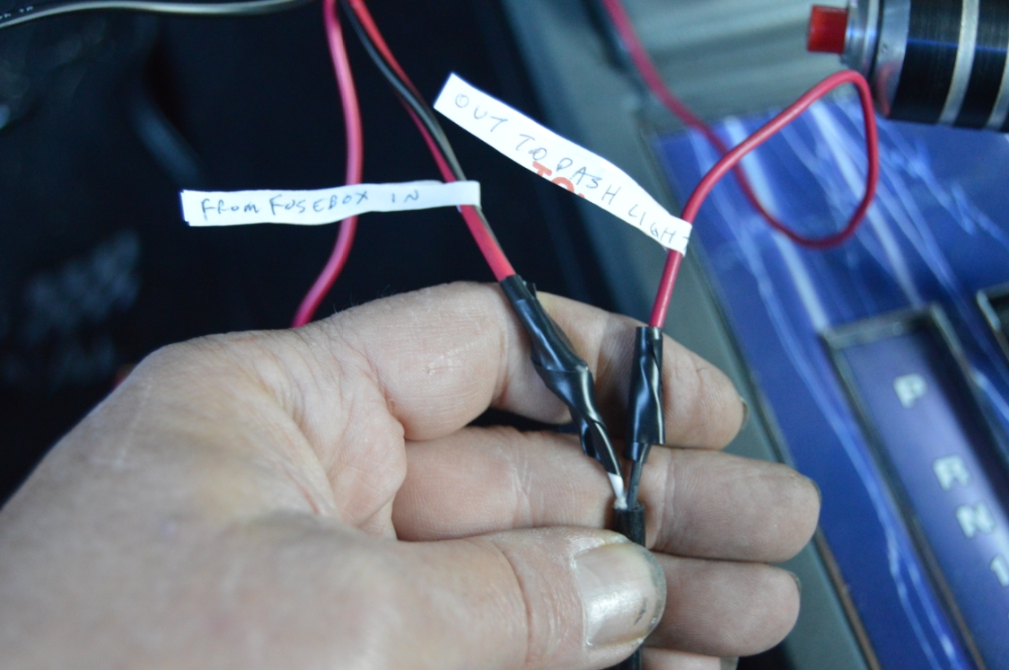
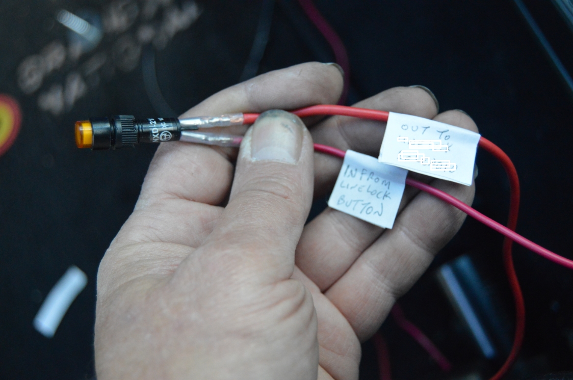
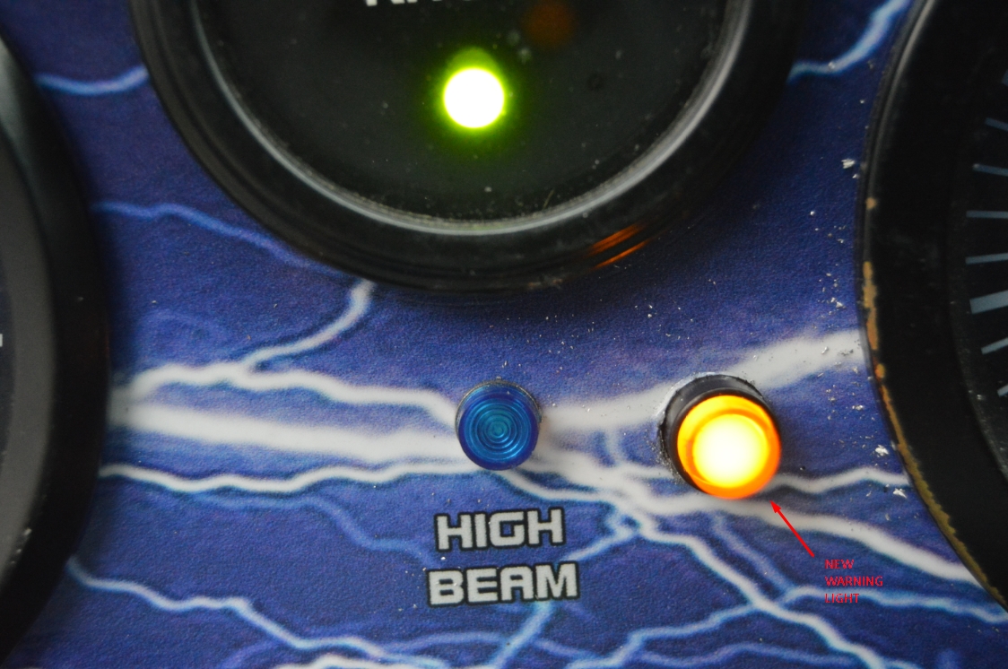
We also have an LED light in the dash that we will be hooking up to this to indicate when the line lock is “on.”
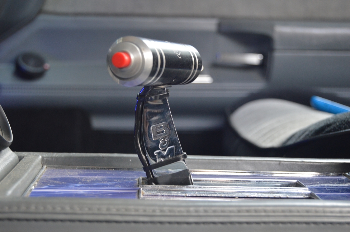
As for the momentary on/off switch, we’re wiring it up to the cool custom made shifter handle button we made.
.
COMPLETION TIME:
1 hour
.
PARTS:
– GNS Complete Line-Lock Kit ($245, GNS Performance)
– teflon tape
– multiple pieces of wire (about 4 feet long total)
– wire connectors (or solder, electrical tape, etc.)
.
TOOLS:
– 7/16, 1/2, 9/16, 11/16 wrenches
– 10mm socket (for bolts on bracket)
.
HOW TO:
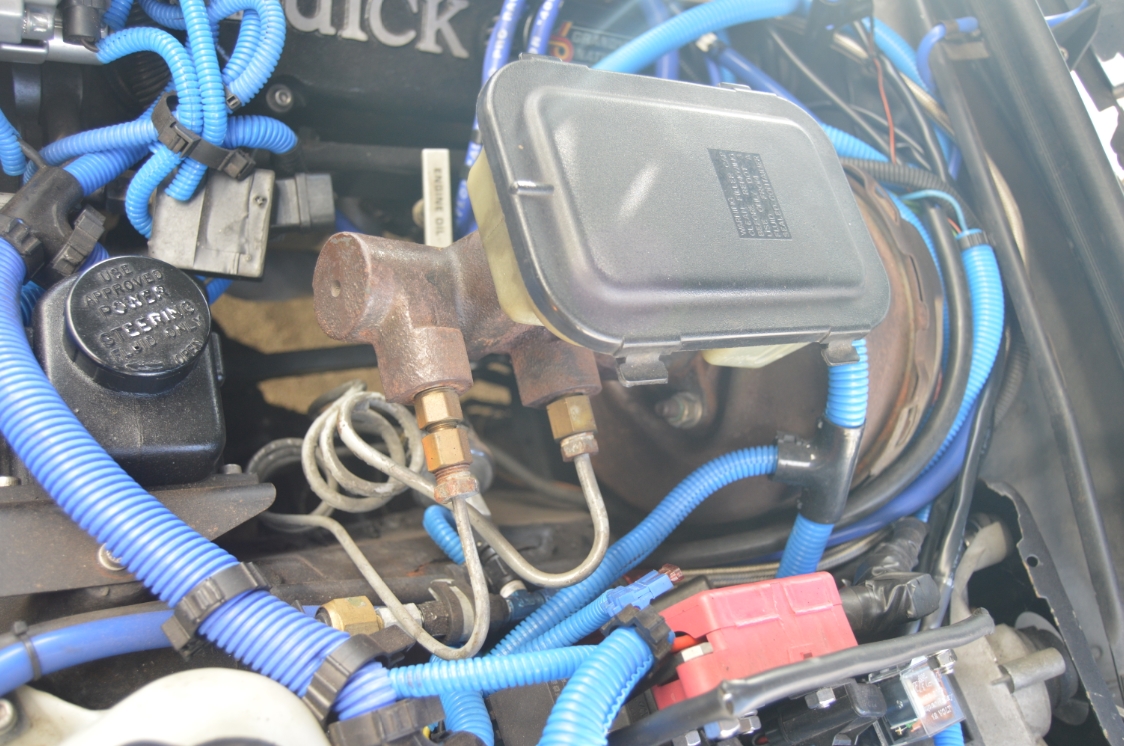
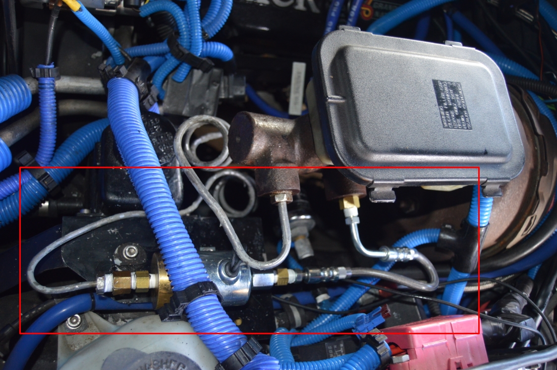
There are vacuum brakes on this 1987 Buick Grand National, so your (Powermaster, etc.) setup may be slightly different.
.
.
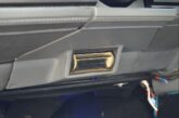
1. Remove the rear line on the master cylinder, which is the front brake line. This is the smaller of the 2 tubes running to the proportioning valve.
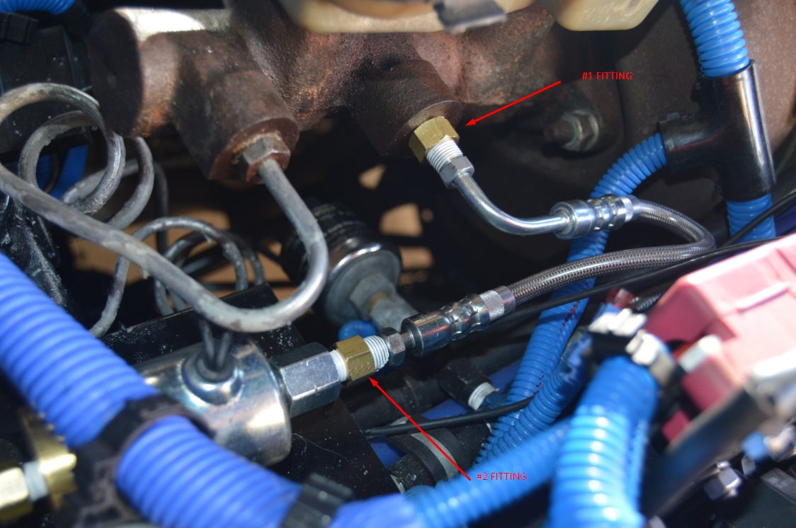
2. Included in the GNS line lock kit are 3 brass fittings, which are marked 1, 2, 3.
Insert the #1 fitting in the rear hole of the master cylinder.
[we used teflon tape on all of the fittings]
3. Insert the #2 fitting in the front hole of the line lock solenoid, which is the silver side.
4. Insert the #3 fitting in the rear hole of the line lock solenoid, which is the gold side.
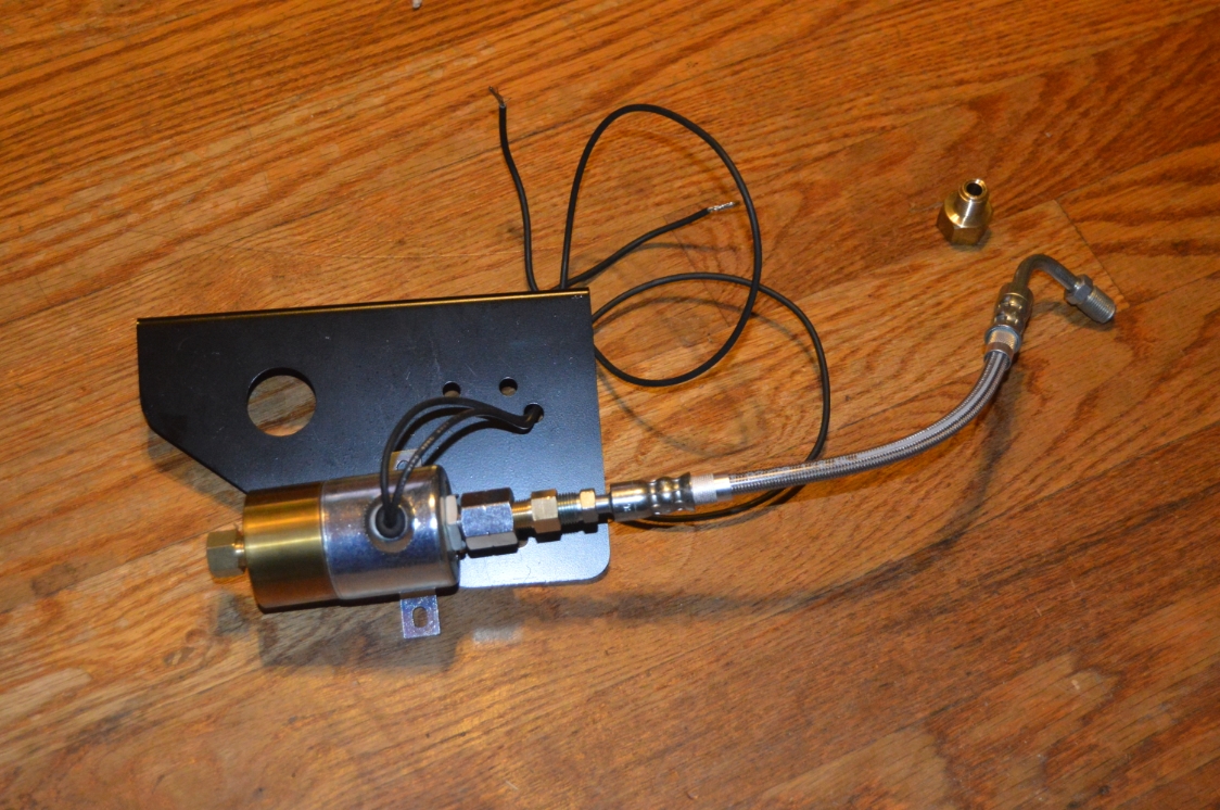
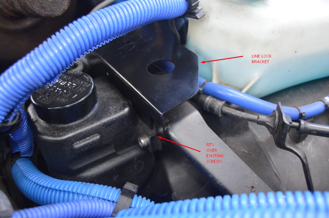
5. attach the line lock solenoid to the bracket using the 2 provided screws.
Run the 2 electrical wires thru the hole that is in front of the solenoid.
.
.
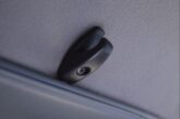
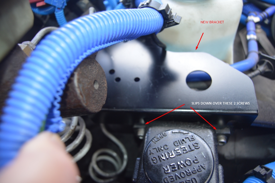
6. Loosen up the 2 (10mm) bolts that hold the power steering pump onto the wheel well.
Remove the stud and nut that is attaching the cruise control cable and clip (from the top of the power steering pump bracket).
You will run this cable under the new bracket.
7. There’s 2 notches in the supplied bracket, which will slide down over these 2 bolts.
Push the bracket down, and tighten up the 2 bolts.
[the bracket fits between the power steering pump and the power steering pump bracket]
8. attach the front brake line to the rear (gold side, OUT) of the line lock solenoid.
9. attach the supplied braided line, the 90* end side, to the rear hole in the master cylinder.
10. attach the supplied braided line, the straight end, to the front (silver side, IN) of the line lock solenoid.
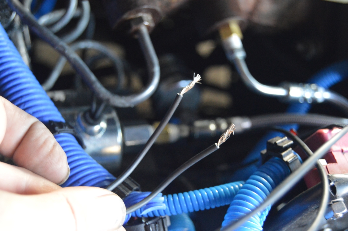
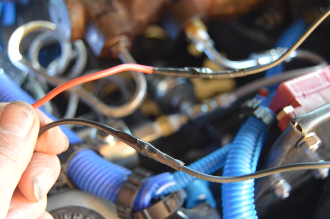
11. The wires attached to the solenoid are 24″ long.
You may need to extend these wires to complete your circuits (to the switch, light, fuse).
You will need to figure out a few things to determine wire lengths and quantities.
– how and where you will supply a power wire from.
– where you want to mount the “in use” warning light.
– where you want to mount the switch.
For the solenoid, it doesn’t matter which wire of the solenoid you use for either of these:
1 of these wires is attached to a ground point.
(the existing wire may be long enough if you ground it somewhere in the engine compartment).
1 of these wires is going to the switch (which is the incoming power to the solenoid).
.
The overall wiring should go like this:
The fuse gets connected to a 12 volt source on one side & the (red wire) from the switch on the other.
The black wire on the switch goes to (either) 1 wire on the solenoid.
The other solenoid wire goes to a grounding point.
The light, gets tapped into the OUTGOING black wire (power from the switch), and the other wire gets grounded.
[DON’T run the power line direct thru the light (bypassing an actual ground ON the light), it may not supply enough outgoing power from the light to the solenoid]
.


.
12. Mount your switch and the warning light wherever you want them.
13. Temporarily remove the fuse from the fuse holder. Wire up one side of the fuse holder to your power source, and connect the other side to the red wire on the switch.
14. connect the black wire from the switch to 1 wire on the solenoid.
13. ground the other wire from the solenoid.
14. From your warning light, tap 1 wire into the black wire from step 14.
Take the other wire and mount it to a grounding point.
15. Key on, engine off.
Push your momentary switch on and verify the light comes on.
You also should hear the line lock solenoid click, verifying that it is working as well.
Key off.
.
.
16. Fill your master cylinder with brake fluid if needed.
17. Key off. Push on the brake pedal several times.
Check the line lock solenoid and connections on the master cylinder for leaks.
Fix any leaks if needed.
17. BLEED YOUR BRAKES!
18. Test the system in a safe, flat surface area.
Start your Buick Regal, put in Neutral, pump the brakes 3 or 4 times, and with the last time holding the brake pedal down, press and hold the switch.
Take your foot off the brake. YOUR CAR SHOULD NOT MOVE.
If it does, something is wrong! Inspect and fix it.
If it doesn’t move, then proceed to slowly press the gas pedal, and eventually your rear wheels should begin to turn, creating a burnout.
If this is successful, then your installation is complete and the line lock works.
[you should again check for any leaks now]
Just FYI, the line lock solenoid should not be engaged for more than 60 seconds at a time.
.
.
NOTES:
Since the bracket is painted, be careful when removing the brake lines! If fluid gets on the bracket, it will crack & peel the paint off!
The brass adapter fittings are very soft (as all brass items are), so use caution when tightening them down! It doesn’t take much to strip, bend or break them!
(as we found out on 1 of the adapters 🙁 )
.
Job done! You will be doing this very soon:

.
.
.
.
The vendor shown above has supplied us with the parts we used in this project, per our request. If you are looking for similar parts, don’t hesitate to inquire with this specific vendor!
.
.