


Instead of cobbling all the wires from the misc accessories (scanmaster, wideband, gauges, etc.) from the turbo buick onto the main fusebox, we decided to add on a new extra fuse panel to handle all of this additional current.
Not only will this modification reduce the juice being drawn from the original fuse box, but it also will spread out the cluster of wires from under the dash (that’s normally ganged up all near the stock unit on the drivers side).
NOTE: some dealers sell an extra fusebox, however, these usually connect to the factory fuse box, defeating the purpose of reducing the power from the OEM unit. You do of course, get the benefit of extra fuses/power sources to tap off of, but in our case, we decided if we were going to utilize this modification we wanted to get the most out of it, thus requiring tapping a new, separate power feed off of the alternator.
TIME TO COMPLETION:
about an hour.
PARTS NEEDED:
A. new fuse box (flat panel, with room for 10 fuses & 12 grounding tabs; $10 off ebay)
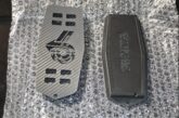
B. power junction box (red, with cover, $12 ebay)
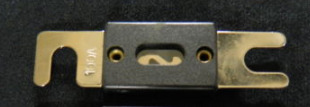
C. 80 amp main inline fuse (ebay $3)
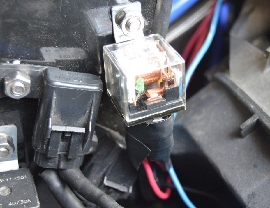
D. 100 amp relay (clear, $10 ebay)
E. 2 zip ties
F. 2- 3/8″ nut & bolt
WIRE:
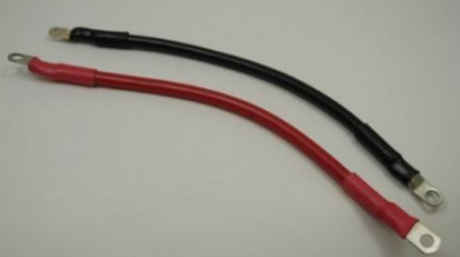
G. 8 gauge (6′ red, from new fusebox to relay)
H. 8 gauge (2″ red, from relay to main inline fuse)
I. 8 gauge (2″ red, from main inline fuse to power junction box)
J. 8 gauge (24″ red, from power junction box to alternator)
K. 8 gauge (6′ black, from new fusebox to engine)
L. 14 gauge (36″ r4ed, from original fusebox to relay)
M. 14 gauge (30″ black, from relay to fender ground point)
TERMINALS:
N. 2 female spade 14 gauge (blue)
O. 1 male spade 14 gauge (blue)
P. 2 female spade 10 gauge (yellow)
Q. 1 ring 14 gauge (blue)
R. 8 ring 8-gauge (gold)
[we mounted inline a power distribution block since this makes a nice access point for any future power sources we may need to add in under the hood. if you don’t require this, simply eliminate it from the steps below & run your main (8 ga) wire direct from the alternator to the inline (80 amp fuse)]
[we had 8 gauge wire on hand in the garage, thats why we used this size, you probably can get away with using 10 gauge wire instead]
[the stand up panel you see the junction box & relay mounted to was created when we had to move the (drivers side) relays during the Buick GNX fender vent install]
>> Figure out WHERE you are going to mount everything (the new fuse panel, relay, junction box) BEFORE you start this project! You may need to modify wire length, etc., based on your choices! <<
HOW-TO:
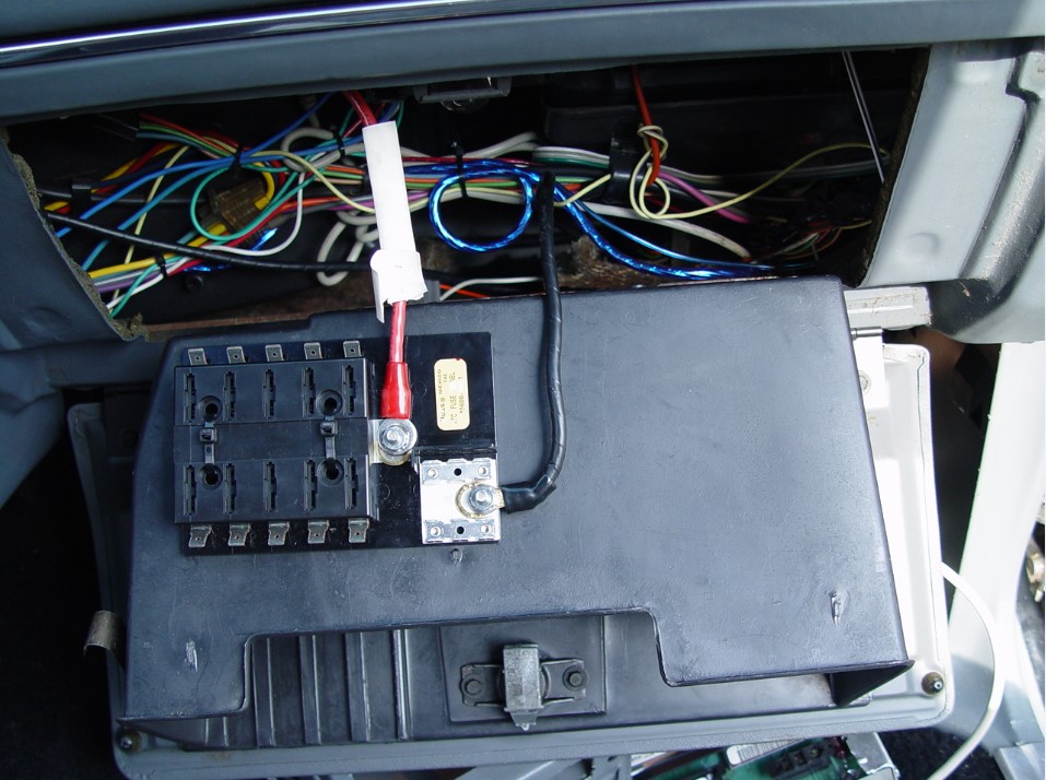
1. We mounted the new fusebox (“A” from the parts list) behind the glovebox, where it will be out of the way, yet accessible when needed. It’s secured to the glovebox via 2 zipties.
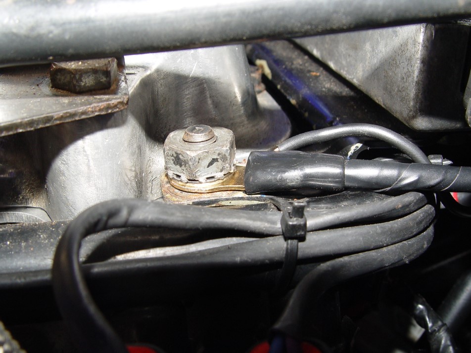
2. connect the new ground wire (“K” from the parts list) from the new fuse box to the engine {we used the bolt on the drivers side where the coil pack mounts}. Run the wire thru the existing hole in the firewall on the drivers side. Use 2 (terminals “R”) on this wire.
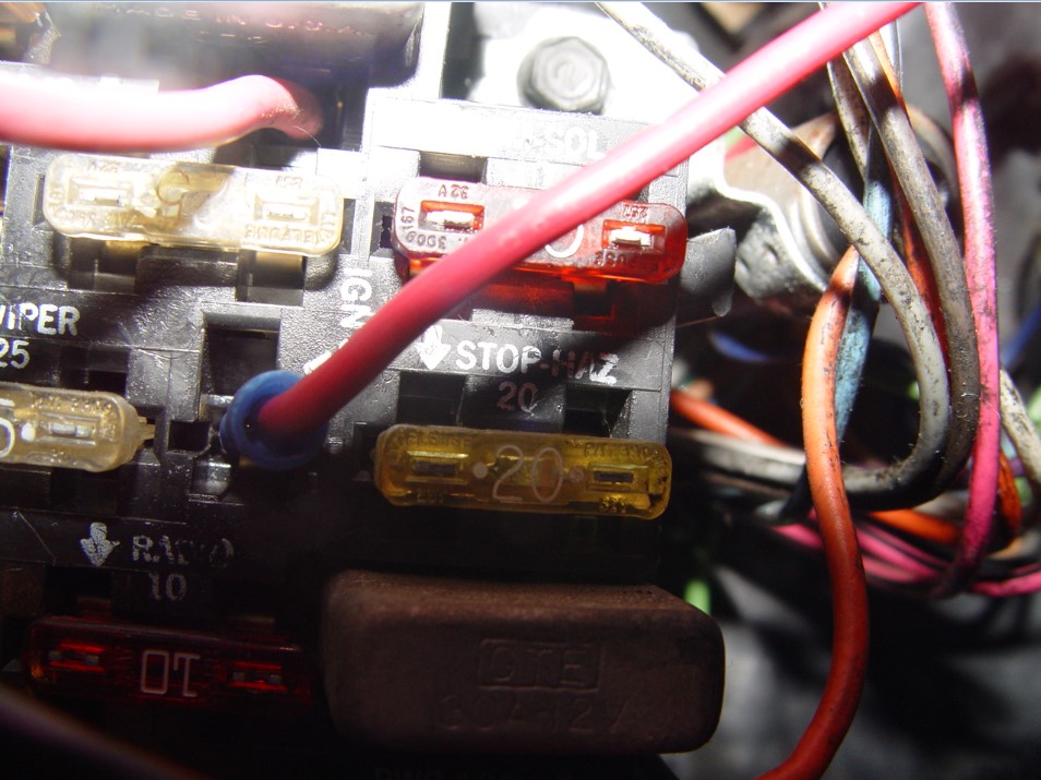
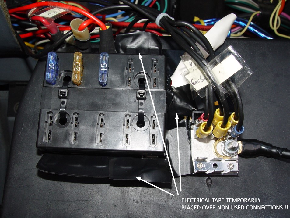
3. connect the power wire (“G” from the parts list) from the new fuse box to the relay (terminal 87). Use (terminals “P” & “R”) on this wire. For safety reasons, you may want to place a piece of electrical tape over the top of the power stud on the fusebox so nothing accidentally comes in contact with this LIVE connection! Same goes for the power tabs that are not being used!
4. connect the power wire (“L” from the parts list) from the factory buick fuse box to the relay (terminal 86). Use (terminals “N” & “O”) on this wire.
5. connect the ground wire (“M” from the parts list) from the relay (terminal 85) to the existing drivers side fender ground point. Use (terminals “N” & “Q”) on this wire.
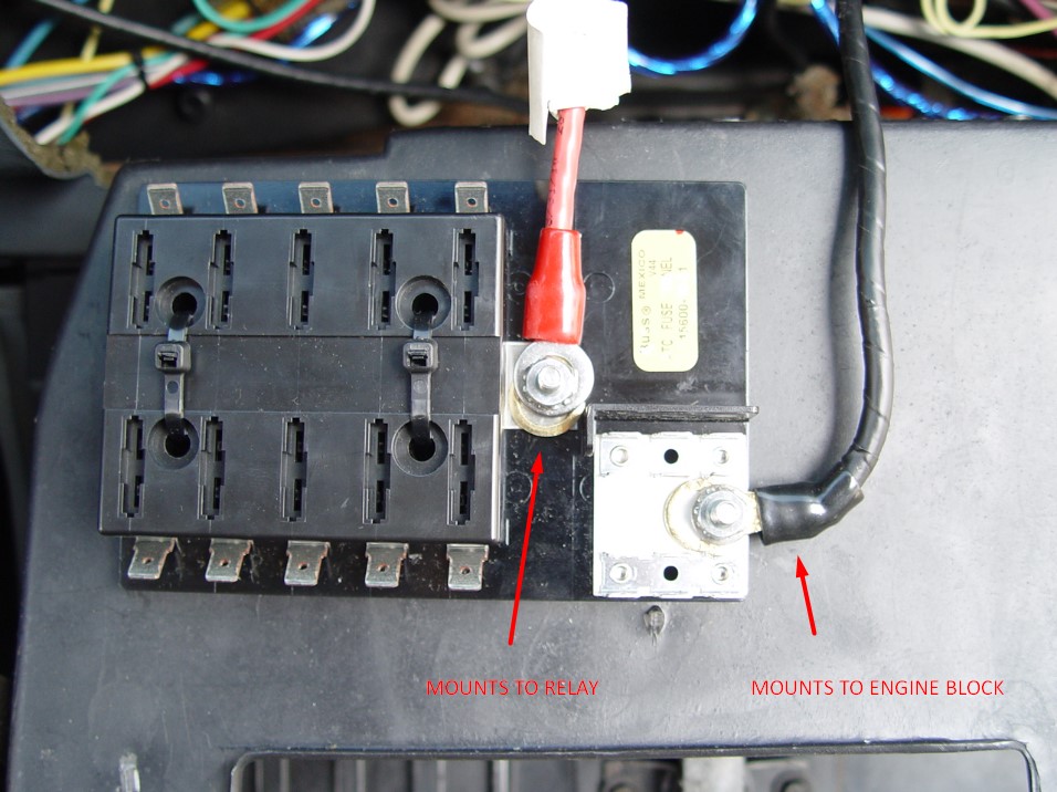
6. connect the power wire (“H” from the parts list) from the relay (terminal 30) to the inline fuse (“C” from the parts list). Use (terminals “P” & “R”) on this wire. To secure the wire to the inline fuse, use the nut & bolt (“F” from the parts list).
7. connect the power wire (“I” from the parts list) from the inline fuse to the power junction block (“B” from the parts list). Use 2 (terminals “R”) on this wire. To secure the wire to the inline fuse, use the nut & bolt (“F” from the parts list).
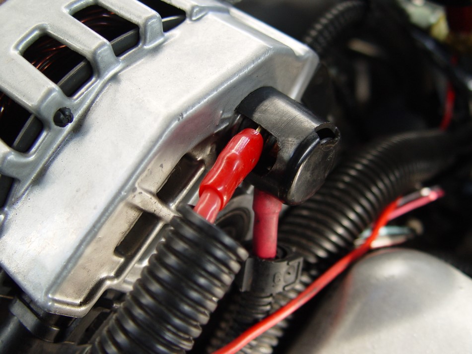
8. connect the power wire (“J” from the parts list) from the power junction block to the (power out) alternator stud. Use 2 (terminals “R”) on this wire.
9. “IF” you have hooked everything up properly, with the key OFF, you should have NO power on the new fuse box between the positive & negative studs.
{note that the ground side of the circuit is ALWAYS grounded (“live ground” – “active ground”), since this is directly connected to the engine}
10. With the key ON (engine off), you should have somewhere around 10-11 volts.
11. With the key ON & engine ON, you should have however many volts your alternator is capable of putting out (about 13.5).
EXTRA INFO:
* the 80 amp inline fuse protects the 100 amp relay, power wires & new fusebox. As long as you don’t hook up a total of more than 80 amps in the new fuse box, all those circuits (in theory) should be protected.
* HOW this all works: the (14 ga) power wire from the stock fusebox is energized when you turn the key on. this turns on the relay, which then allows the new (8 ga) electrical wire to supply the new fuse panel with power.
.
>>> PICTURES ARE IN NO PARTICULAR ORDER & DO NOT REPRESENT ALL OF THE NECESSARY STEPS FOR COMPLETION OF THIS JOB! (read the story for the complete how-to) <<< .


.