


Yesterday, we finally finished building our custom home made center console for the Buick Grand National.
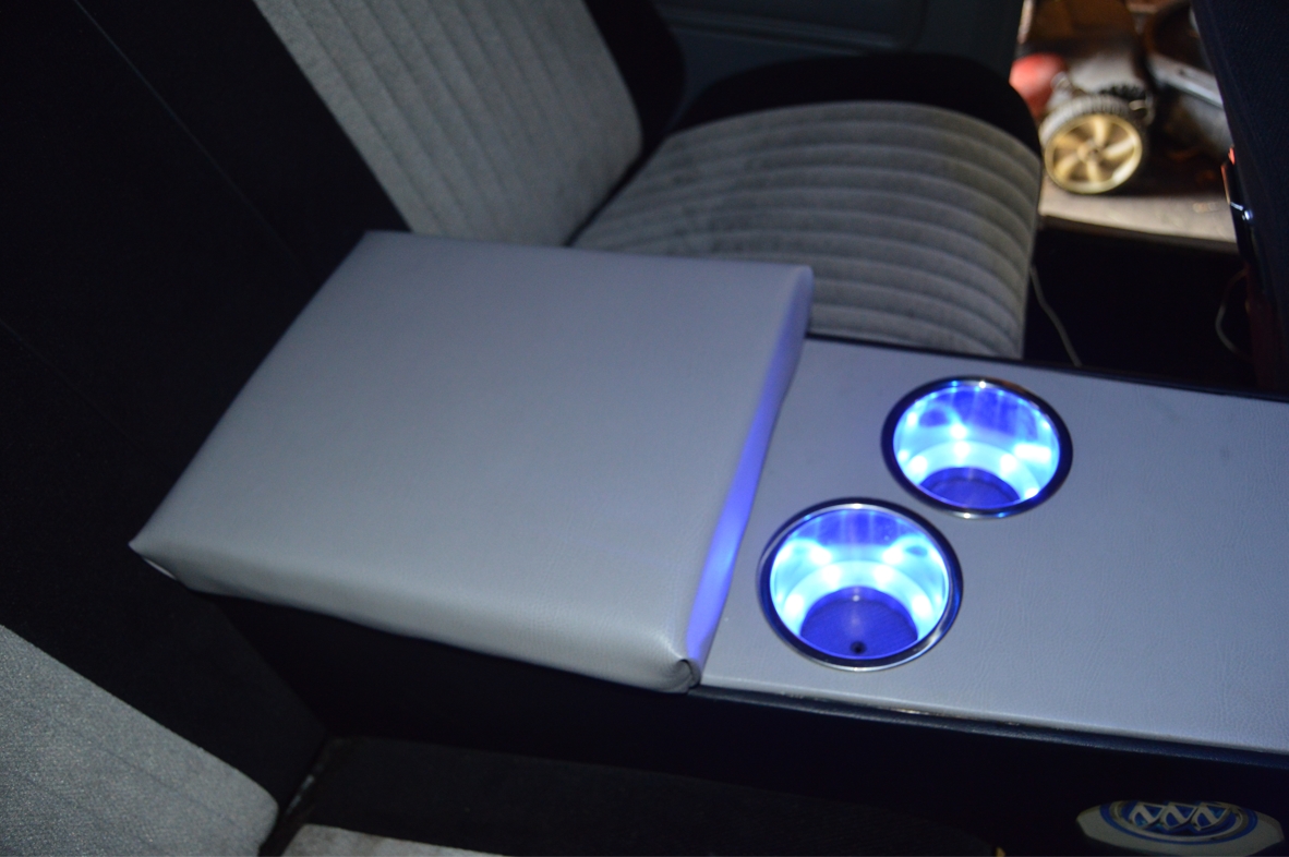
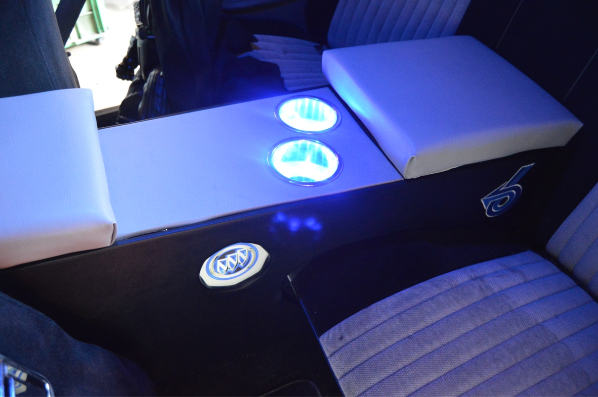
Today, we finalize it, by wiring up all the lights (the cupholders & custom backlit tri shield emblems), and add the remaining small items.
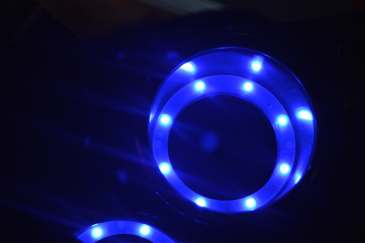
We only mentioned this briefly previously, but we decided to put some lights on the sides of the console, to jazz it up a bit, but also to serve another purpose.
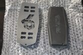
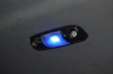
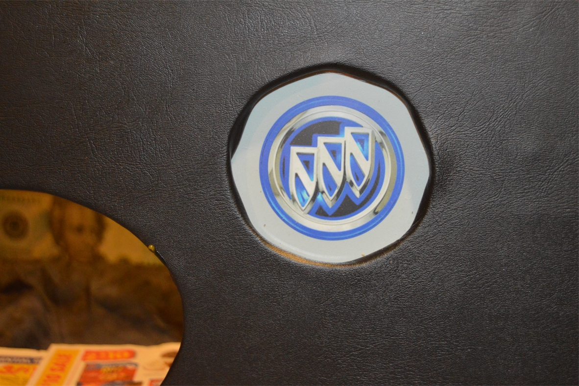
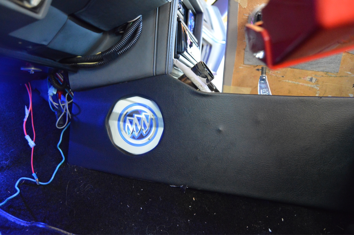
Not like others have done however (like the common long LED strips usually used for console projects), but a custom backlit image of the Buick Triple shield logo!
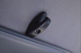
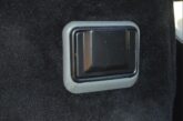
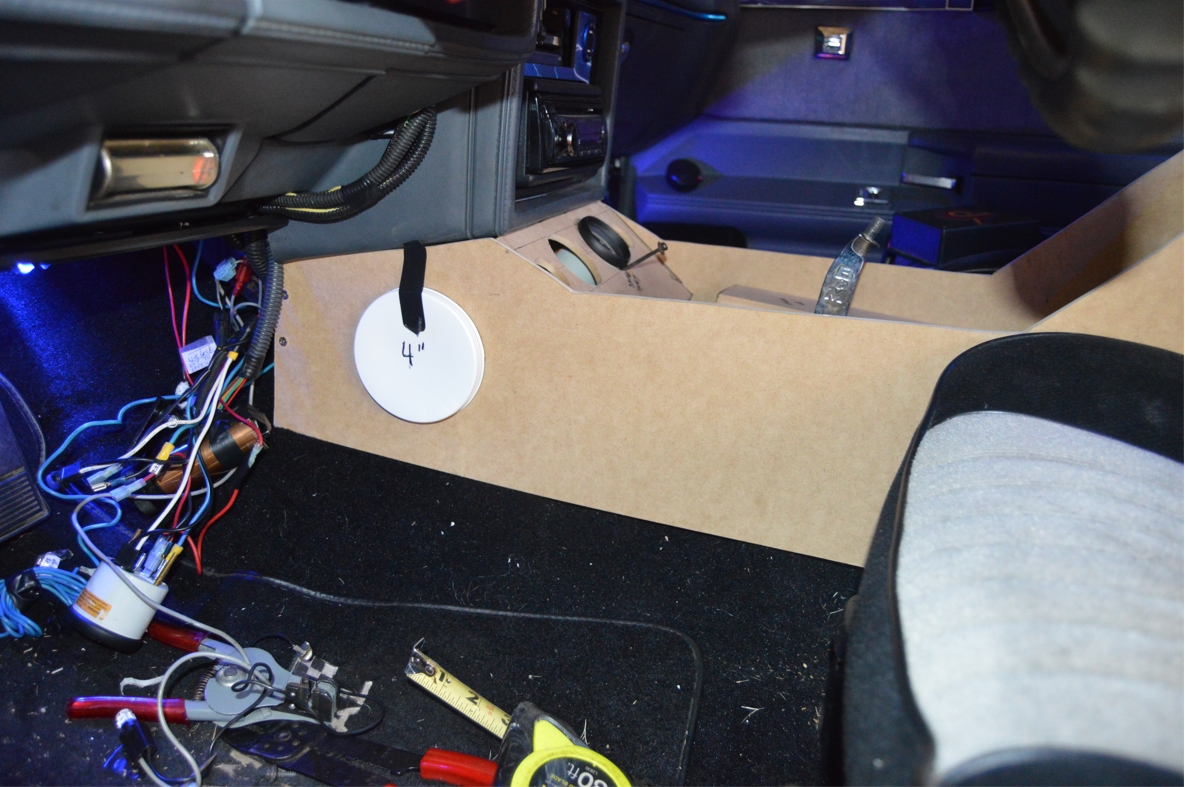
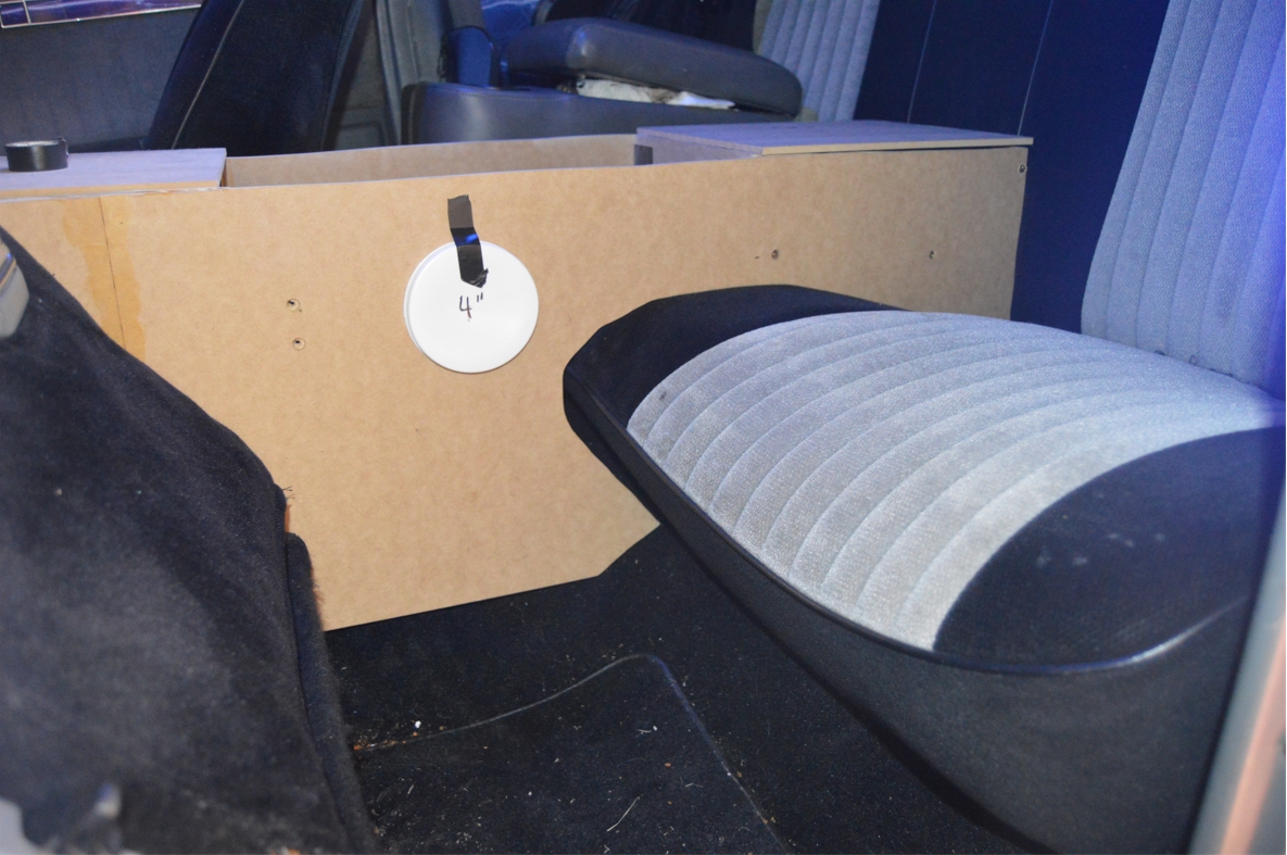
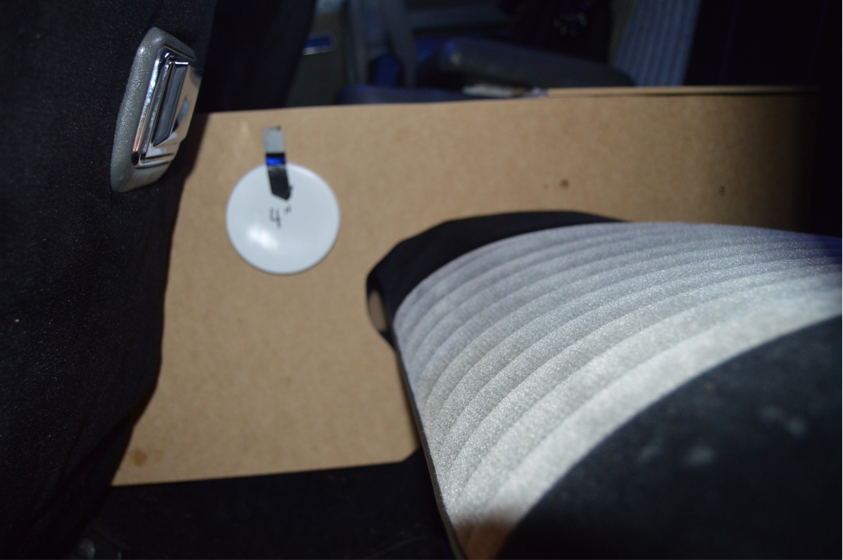
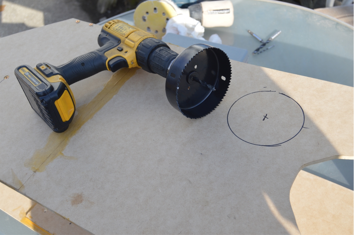
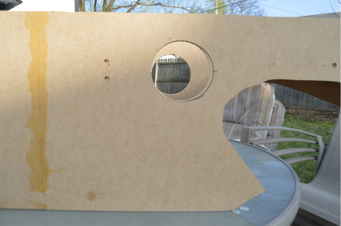
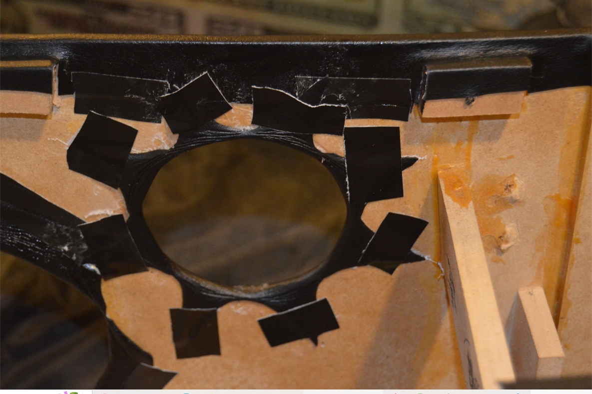
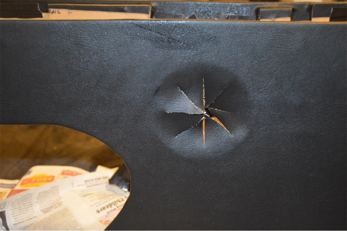
From the outside of the console (on both sides of the front and rear ends), you see a 4″ round hole, with a (3″ round) Buick tri shield emblem within this area. A cool looking image that fits well within this Gbody Regal.
With lights shining behind it, which serve to light up both the front and rear floors, not only when the running lights are on, but they also light up whenever the doors are opened!
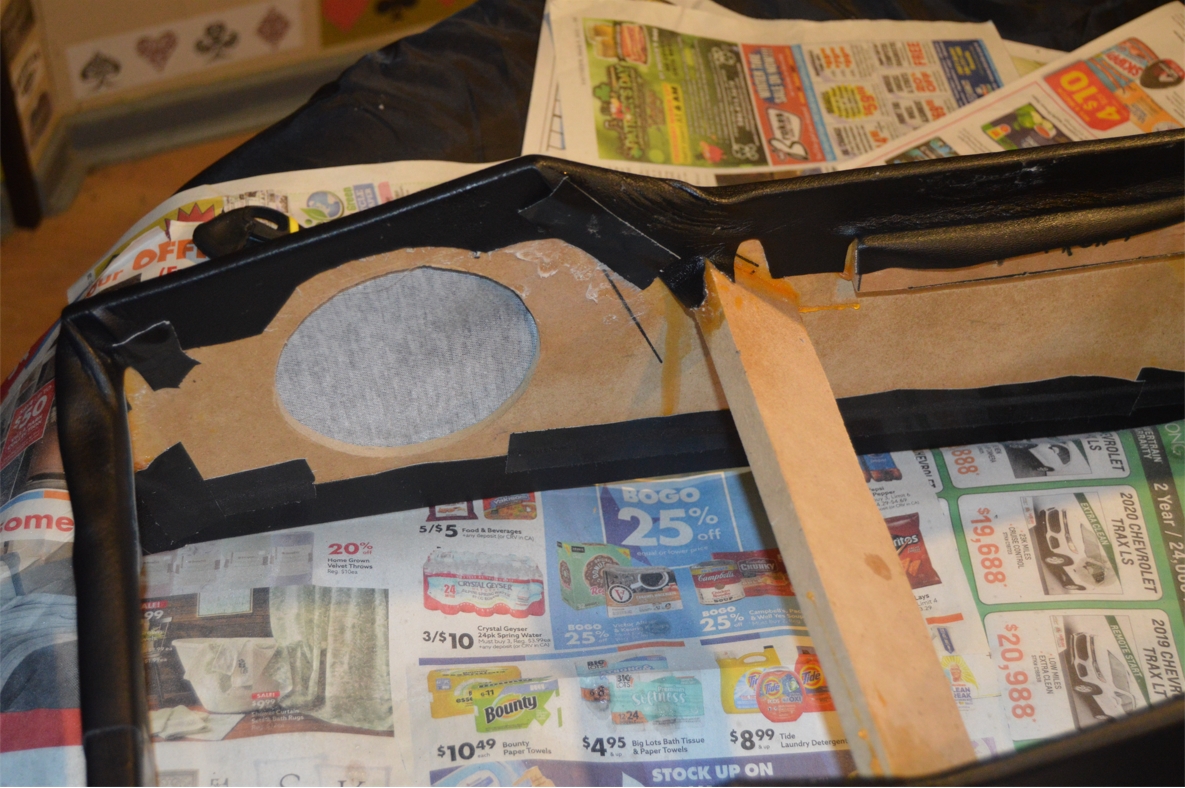
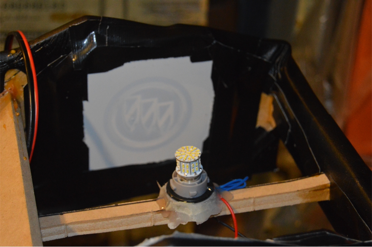
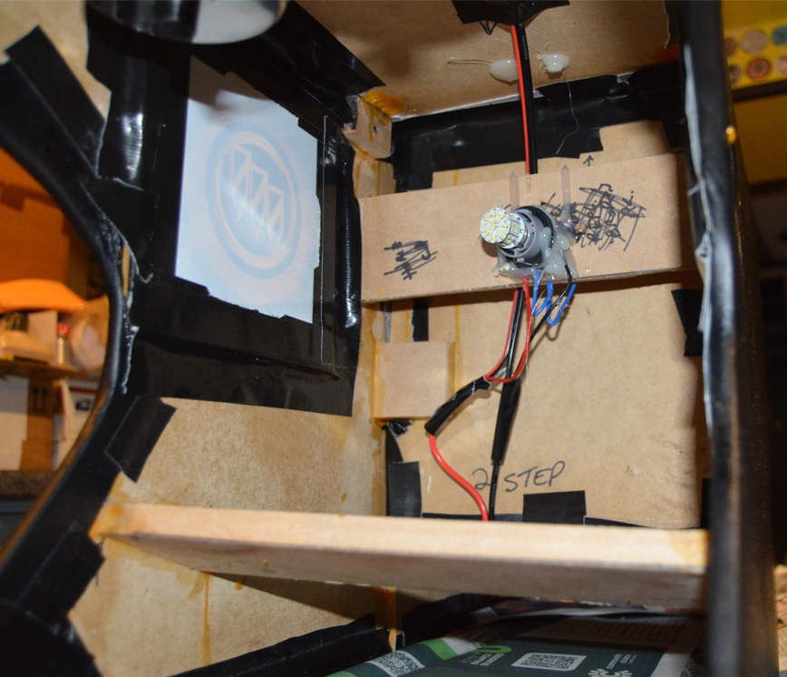
From the inside (underside) of the console, it’s actually created by sticking a backlit decal onto the front side of a 6″ square piece of plexiglass, which is attached to the (inner) sides of the console.
The plexi is glued onto the inside of the console to hold it in, centered within the 4″ hole (leaving 1″ all around to secure it to the console).
.

.
For the locations of the holes we made in the console:
FOR THE FRONT:
We made the holes 1″ down from the top, and about 3.25″ away from the very front, as viewed from the side.
FOR THE REAR:
The holes are centered (left to right, looking at it from the side) between the back of the front seats, and the front of the rear seat (bottom portion).
The top edge of the hole is 2″ from the top of the console.
.

.
.
Two relays are used for lighting purposes, and are mounted near the front of the console (on the bottom of the gauge panel).
.

.
[note, we wanted all 4 of the side lights and all 4 of the cupholders to light up when the doors get opened, as well as turn on when the running lights are on. So we connected ALL of the power wires for all of these items together. The same was done for all of the negative wires. Then these wires were plugged into the relays]
Wiring these up with their dual purpose circuits presents a bit of a challenge.
To get them to function when the doors open up, requires them to be connected to the dome circuit in the car, which is a negative triggered wire.
(meaning the lights always have power running to them, and only actually turn on, when they are grounded, via the door jam switch)
To get them to function when the running lights are on, is totally backwards from the above.
A normal circuit like this (usually) is grounded, and turns on the light when power is applied.
To get around this dilemma of one circuit being triggered via ground, and the other being triggered via power, we are using a separate relay to control each circuit. This will prevent any backfeed from entering either system and causing it to malfunction.
We wired all these lights together; all the powers were connected together, with a short (6″) wire lead added. The grounds were done the same way, except 2 leads were attached to the group of ground wires.
.

.
Relays always serve a useful purpose, and aren’t hard to implement when you know how they function.
Just think about it this way, a relay is like 2 circuits in one, when the first circuit is completed (“turned on”), the second circuit turns on. If the first is NOT completed (NOT “turned on”), the second circuit can NOT turn on.
circuit #1 in the relay:
terminal 86 is old/original incoming power (or trigger) wire.
terminal 85 is for a ground wire. (can be a new wire that you ground somewhere)
When the above 2 terminals complete their circuit (power goes into relay, then out of the relay and gets grounded), THEN the 2nd circuit of the relay gets turned on.
circuit #1 ALWAYS needs to be a power (terminal 86) and ground (terminal 85) to make the relay work.
(it doesn’t actually matter where the power/ground comes from, can be an existing power/ground, or a newly made power/ground)
The benefit of this 2nd circuit (in the relay), is that it can be used for transferring power OR ground.
Meaning the 30 & 87 terminals can be BOTH a ground wire,
or both these terminals can be used as a power wire to feed something.
These 2 terminals (for circuit #2) should NEVER be a positive AND a negative wire.
This is a feed-thru circuit, whether positive or negative.
(in thru terminal 30 and out from 87)
(generally, this 2nd circuit is used to feed power, like terminal 30 will come from the alternator or battery, and terminal 87 will supply your new accessory with power – such as in hotwiring the fuel pump)
(but in our use here, we are making both of these terminals ground wires to perform what we need to do for these lights to work properly)
To use the second circuit (of the relay) as a power feed:
terminal 30 is a new incoming (usually a heavier gauge wire) power supply (from battery, alternator, fusebox, etc.) to the relay.
terminal 87 is the outgoing power wire (from relay) to feed whatever item that needs (switched) power (also a heavier gauge wire).
(remember, this item will ONLY get its power when the first circuit, terminals 86 & 85 are complete)
To use the second circuit (in the relay) as a ground:
terminal 30 gets connected to a ground source (battery, frame, etc.).
terminal 87 supplies the item with a ground.
Your item will ONLY be grounded when the first circuit is complete.
Now, we are going to make our (side triple shield) lights “ground triggered” for both systems (the dome, and running lights) that will turn them on.
This means that these lights will have constant (active) power to them, but will only “turn on” (light up) when they actually get grounded.
We connect the (red) power wires from the lead on our lights to a fused power source.
(or run a new fused wire from the fusebox)
So, relay #1, which is for the door opening / dome circuit.
We connect the (black) ground wire from one of the leads on our lights to terminal 87.
terminal 30 gets grounded to any good ground source.
(this is the #2 circuit of the relay, and won’t be triggered, or turned on, until the #1 circuit on the relay is completed)
(the below is the #1 circuit, for relay #1)
terminal 85 gets tapped into the door jam switch wire for the dome circuit.
(use the door jam switch WHITE color wire – which is the ground wire)
terminal 86 gets connected to any power source (or run a new power wire from the fusebox, but make sure its fused!).
What will happen, is that since the relay already has constant power (terminal 86), WHEN the door opens (completing the terminal 85 ground circuit, and thus completing circuit #1 on the relay), the relay will “turn on” circuit #2 (terminals 30 & 87).
Since 30 & 87 are ground wires, and the terminal 87 is connected to the lights (negative) wires, those wires are now “live” grounded.
The lights already have constant power going to them (off that lead), so they will light up.
That’s the first part of this equation, getting them to light up when the doors are open.
.
Now onto the second half.
Relay #2.
We need the components to light up when you turn your park (running, head) lights on.
The lights already have constant power connected (from above) to them.
We just need to use relay #2 to complete the ground circuit.
The other (black ground) lead off the bulbs, gets connected to terminal 87.
Terminal 30 gets connected to a ground source (battery, frame, etc.).
Terminal 85 gets connected to a ground source (battery, frame, etc.).
Terminal 86 gets connected to the HVAC light, the GRAY (power) wire.
What happens here, is when you turn your regular running lights on, (power) triggering terminal 86, and terminal 85 is grounded, thus completing circuit #1 on the relay.
Circuit #2 is now turned on because of that, and the ground wires from terminals 87 & 30 supply a ground to the bulbs, which makes them stay lit.
So now those lights are finished being wired up.
.


.
.
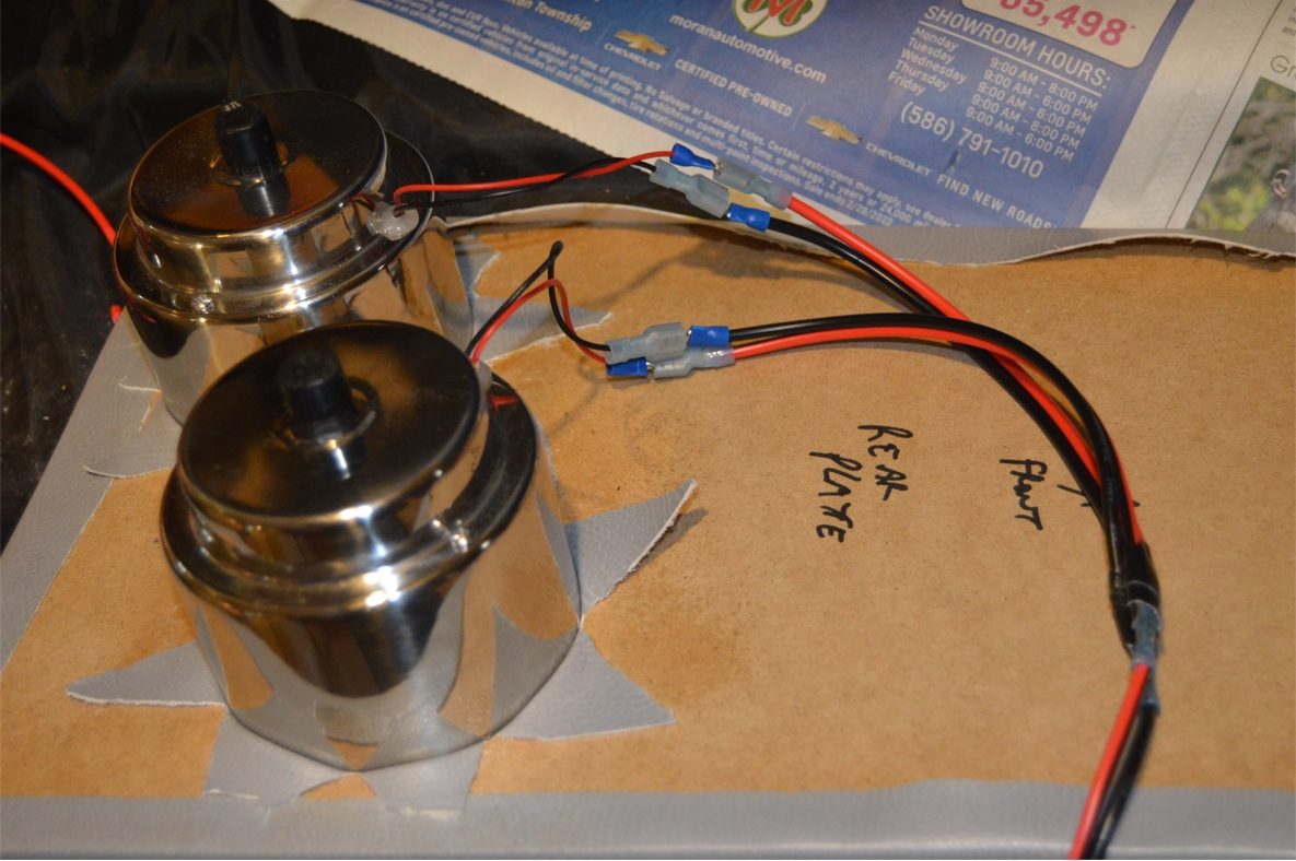
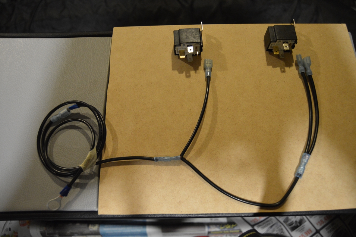 [quick wiring tip: for the ground wires that say “ground source” for the relays (above), these can all be connected together, and grounded at the same place. we connected these together using 6″ leads for each. We did this for both relays. Then we took those leads and connected those together. The single outcoming wire was then grounded. See pic to the right]
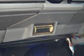
Note that when we made the wiring for the cupholders, since these are simply set into the holes created for them (and not actually secured down), we included an extra 12″ of wire, to allow the cupholders to be pulled out a distance, and drained, if ever needed.
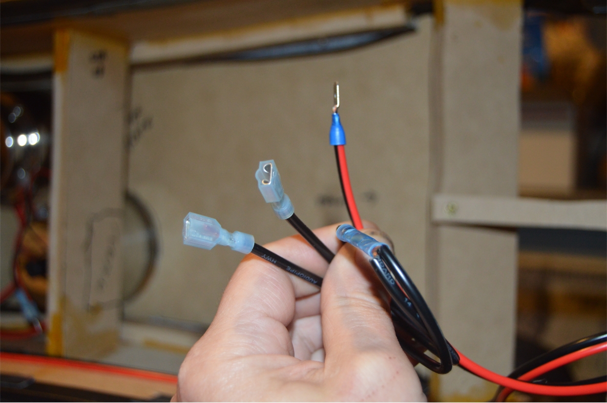
[also, all of the wiring connections have quick connect terminal ends on them, so they are easy to disassemble, if needed]
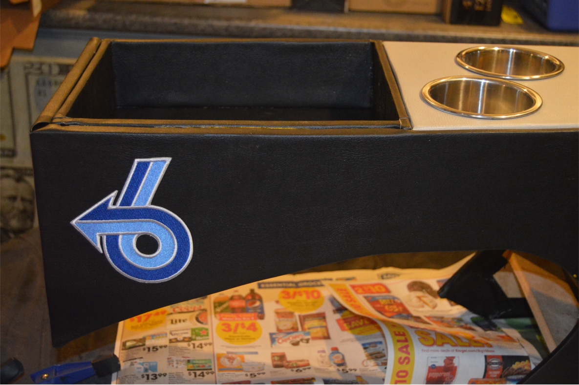
2 final additions.
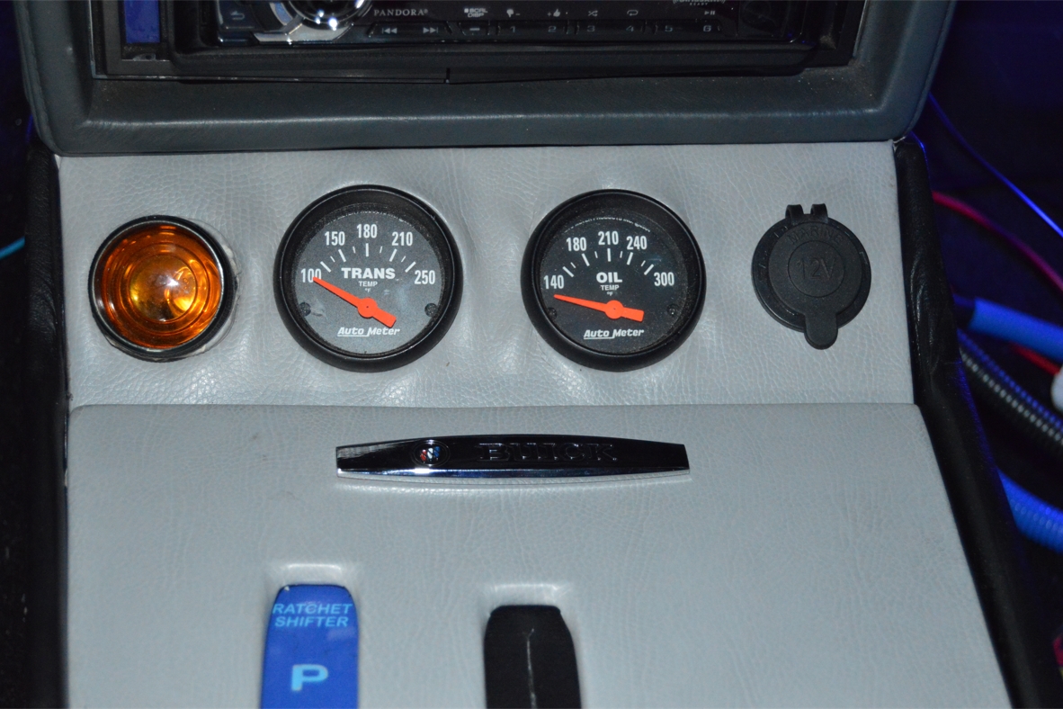
We mounted the chrome Buick nameplate under the gauges.
We ironed on the cool custom Turbo 6 patches to the rear sides of the console.
.
.
Be sure to come back tomorrow for the final installation of this new center console into the 1987 Buick Regal Grand National!
.
This is an ongoing series about creating a new custom center console unit for a Buick Grand National.
See the steps taken below to create (will be linked after publication).
.
Find the first part (thoughts, plans) here:
Custom Center Console for Buick Grand National (1 of 7)
Find the second part (specs, parts, building template mockup) here:
Custom Center Console for Buick Grand National (2 of 7)
Find the third part (wood size choices & the weight differences) here:
Custom Center Console Buick Grand National (3 of 7)
Find the fourth part (prep work, cut out parts) here:
Custom Center Console Buick Grand National (4 of 7)
Find the fifth part (building the console) here:
Custom Center Console for Buick Grand National (5 of 7)
Find the sixth part (wiring up all the lights) here:
Custom Center Console for Buick Grand National (6 of 7)
Find the seventh part (installing the console) here:
Custom Center Console for Buick Grand National (7 of 7)
.