


Now that winter is finally done with, we’re raring to go on continuing with working on the 1987 Buick GN.
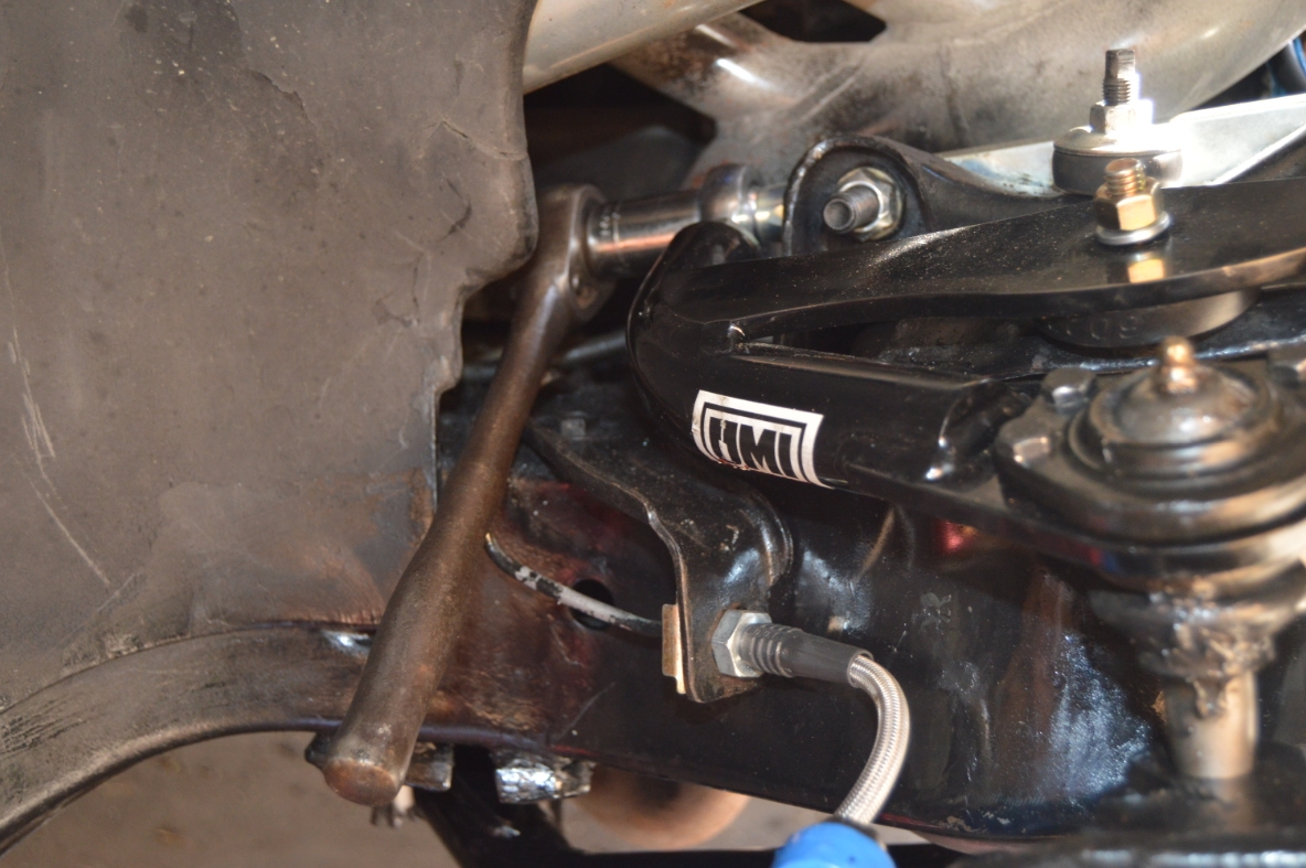
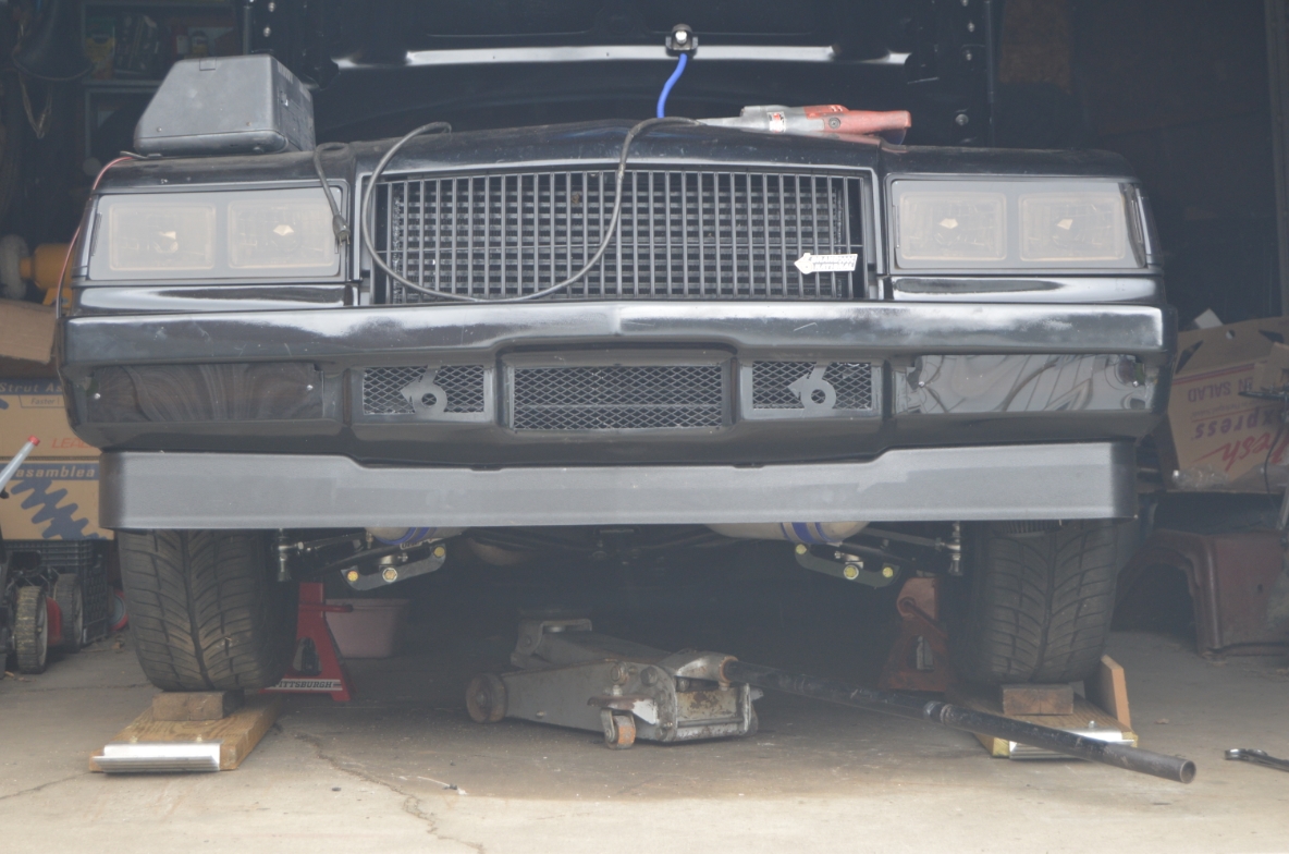
The front end of this ’87 Buick Grand National has been getting a lot of love lately.
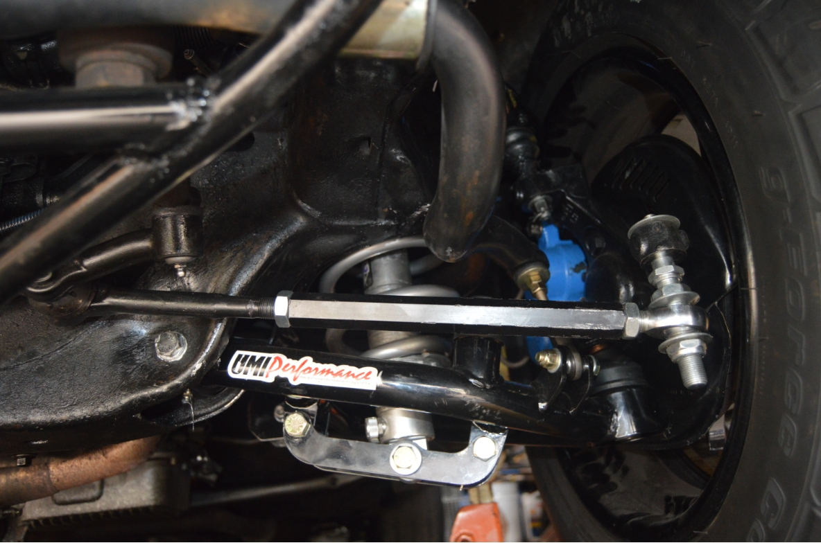
We installed new tubular a-arms, a bump steer kit to go along with the steering rebuild kit, as well as some custom touches to the upgraded disc brake calipers!
When we finished up doing all of the above (right before the snow started falling), we never got around to performing the much needed front end alignment to set things straight with all the new parts.
So now is the time to get ‘er done!
A do it yourself alignment isn’t real difficult, assuming you have some proper tools to perform such a task, and the willingness to attempt such a job.
It is kind of time consuming however.
We followed the instructions from a video we previously posted on here, and went ahead with the procedure.
The first thing we noticed, was that both tires were pointing outward slightly (meaning the toe needs adjustment). This must somehow be because of the new a-arms, as previous to installing them, on the old front suspension, things seemed aligned pretty well.
(not that it was checked, but there wasn’t any unusual tire wear, and the GN tracked straight down the road)
.
.
COMPLETION TIME: 2-5 hours depending how much you need to adjust!
(the caster/camber part took us 1.5 hours, the multiple toe setting attempts took another 1.5 hours, with figuring out about cutting the inner rod end & sleeve & actually doing it took another hour. Plus an hour of online research about the bump steer kit. That’s 5 total hours messing with this, good thing we like to work on this Turbo Regal!)
(might be worth just taking it in to a shop to get aligned, but then you have to deal with towing if your current alignment is as far off like ours is. So time vs money)
.
TOOLS NEEDED:
* floor jack
* jack stands
* angle finder, or level gauge
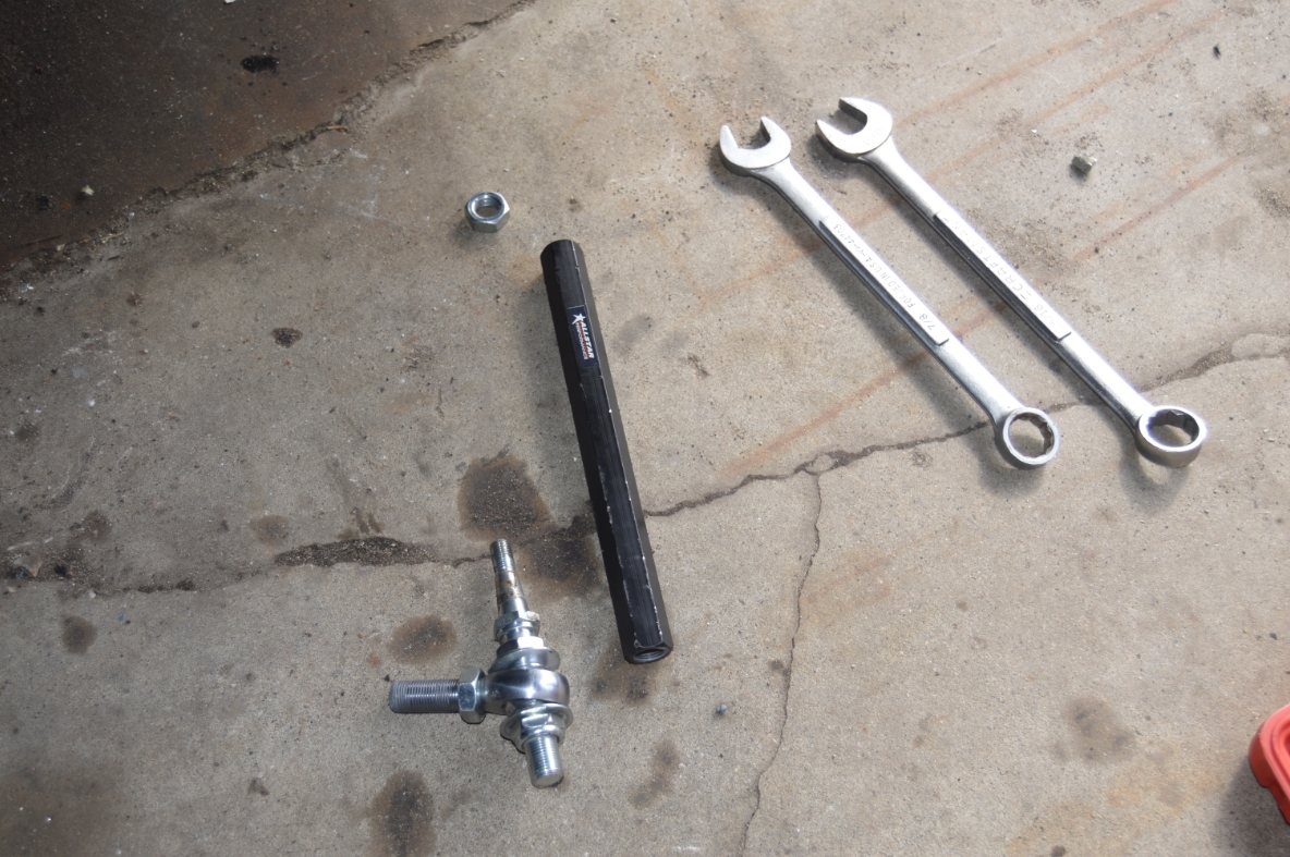
* 3/4″ & 15/16″ wrench (to adjust the aftermarket upper a-arms. cross shaft, jam nut)
* stock tie rod adjuster sleeves use 1/2″ or 9/16 nuts
* 5/8″ socket to remove outer tie rod end
* ball joint separator
* pliers (cotter pin removal)
.
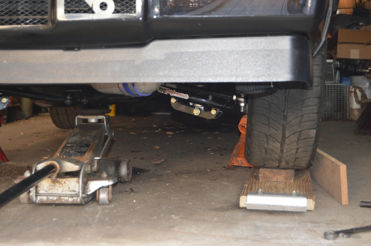
We already have the car supported via jack stands (on the frame, in front of the doors), and the wheels are off the Turbo Buick. That’s how the G-body Regal was left the last time we worked on it.
.
ADJUSTING CASTER / CAMBER:
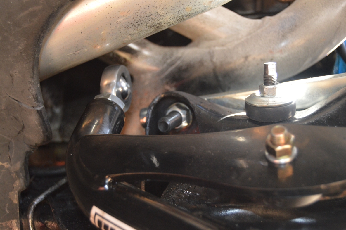
Caster/camber adjusting on OEM upper arms is accomplished by adding/subtracting shims between the a-arm’s cross shaft and the frame mounting point (shims get put on the bolts). That moves the arms in/out depending on how many shims you put in there. In general (but not always, depending on your specific G-body frame), the rear bolts usually have more shims on them than the front side does.
The UMI arms we have (supposedly) require no shims at all (one of the reasons we selected these specific arms). They are adjusted by simply spinning the bolt in/out and locking it in with the jam nut.
For a starter setting, we have the bolts turned in as far as they will go.
(a couple other Buick guys have these same arms set this way, so we figured it’d be a good starting point)
.
IMPORTANT!
One thing to remember, is that when adjusting caster or camber, when you adjust one of those, it may affect the other. Meaning make sure you always check BOTH settings after you adjust each one. And once you are done with all final adjustments, recheck BOTH settings again!
For maximum performance setups, YOU should be in the drivers seat, or place an equivalent amount of weight on the drivers seat. Also, the suspension (travel) should be mocked up to a height of where the car sits at while going down the track (or street).
.
FIRST CHECK ON CAMBER BEFORE MAKING ANY ADJUSTMENTS:
.
.
CAMBER:
(negative camber makes it easier to turn the car. Camber is when the top of the wheel is angled towards the middle of your car)
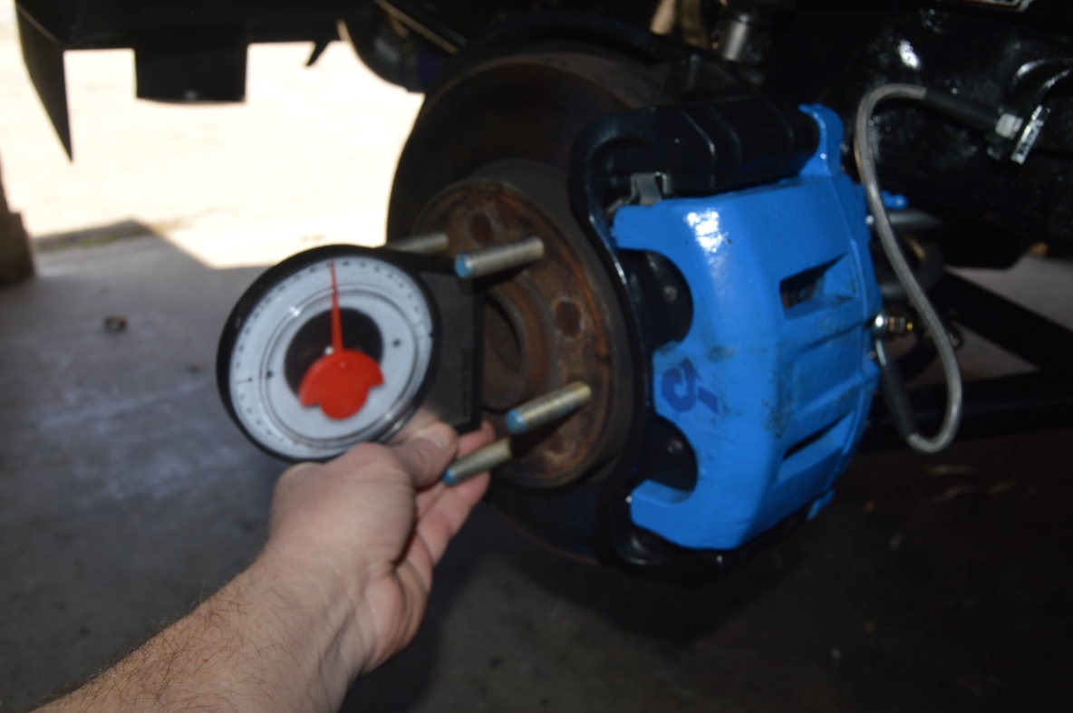
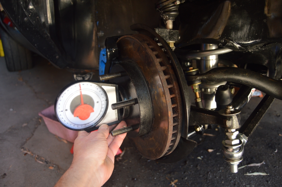
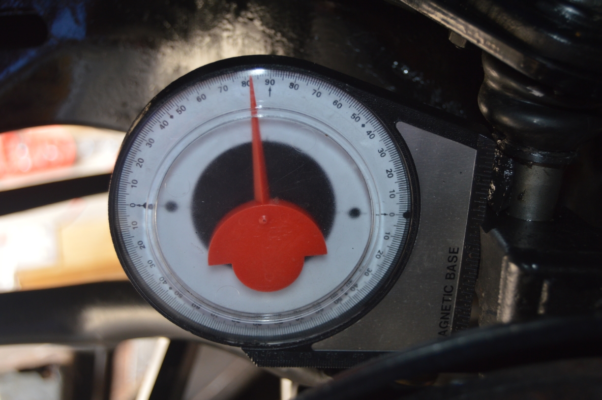
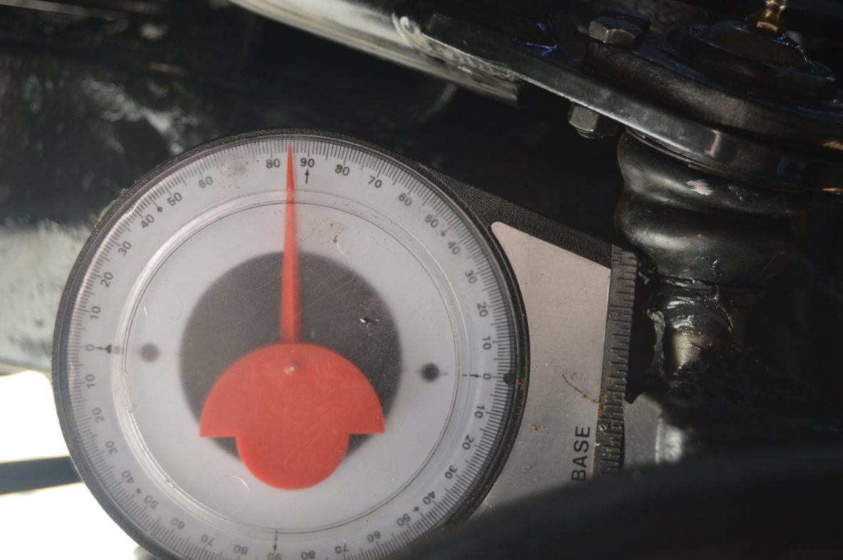
Place the angle finder on the axle hub.
Our reading says it is at “0” on both sides (before adjusting anything).
(you use the 90 degree mark on the angle finder as “0” vertical and add/subtract from there. Our reading said 90, so this translates to 0 degrees of camber)
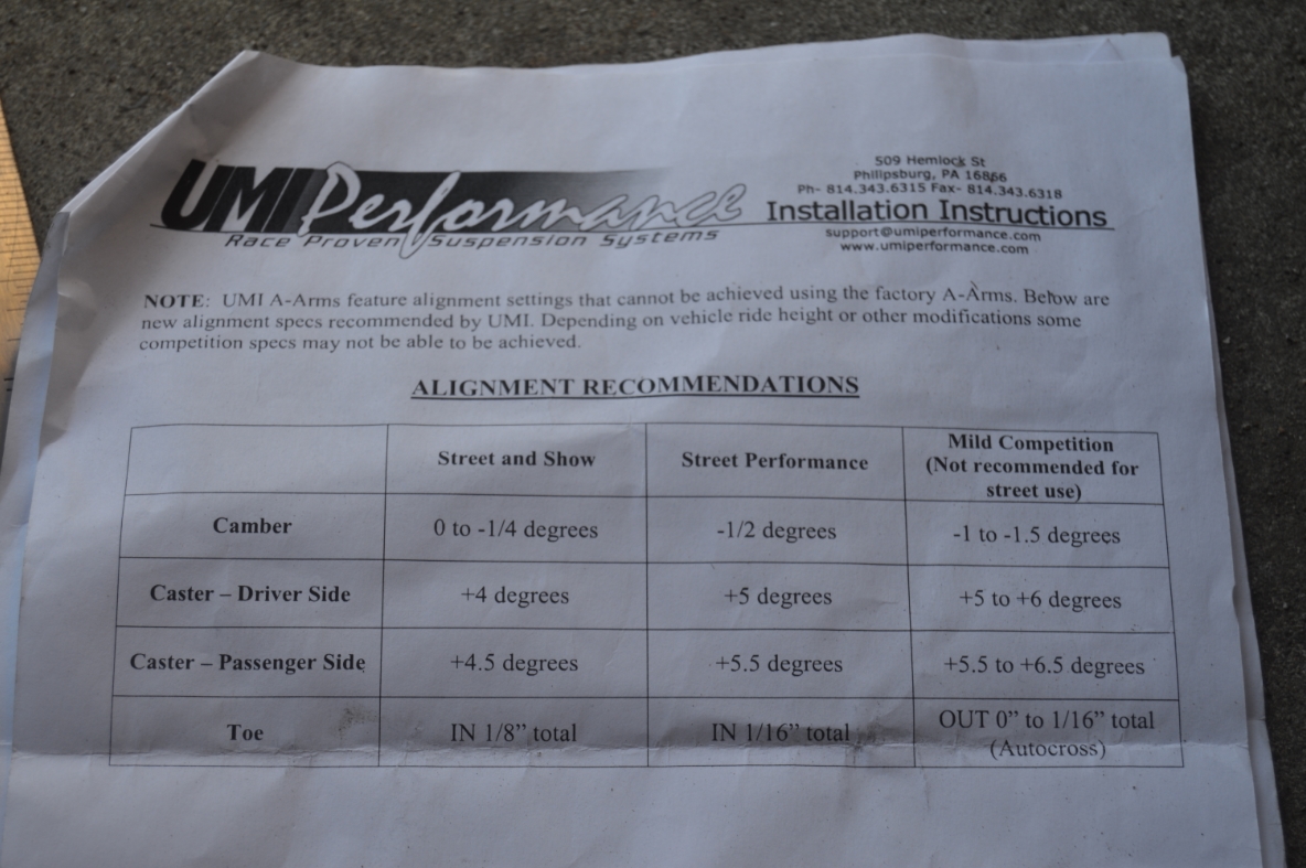
The recommended specs state 0 to negative .25 degrees of camber.
For now, we are going to not adjust it and leave it where it is.
(since adjusting the caster may change this number)
.
[ just FYI, after we adjusted caster, the driver side was still at 0 for camber. The passenger side however, was at -1 degree. Wanting them to be relatively close to each other, if not absolutely 0 on both sides, we had to put 1 shim (a washer spacer) on the passenger side upper arm, on BOTH the front AND back bolts to get it to be 0 – that way with an equal washer on front and back, all it did was brought the entire arm inward the same amount, without affecting caster. ]
.
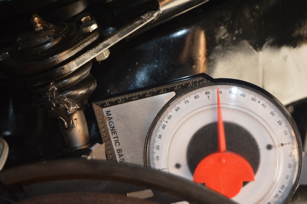
CASTER:
(caster is the spindle angle of the upper/lower arms compared to each other, against true vertical. On these particular arms, the lower pad is more forward, to the front of the car, than the upper one is, indicating positive caster, even though that sounds backwards. The top of the spindle should be pointing toward the back of the car for positive caster)
These UMI arms according to the specs, have a total of 10 degrees of possible adjustment.
We measured the angle as is with the starting setting we used, and the passenger side is at 10 degrees, the drivers side is 10 also.
(so that’s the max, with both rod ends fully in)
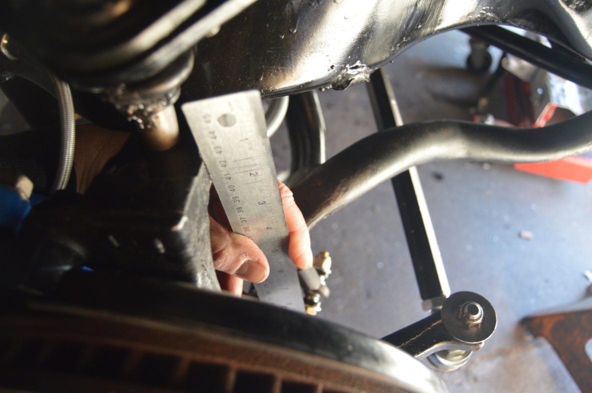
You are suppose to measure the caster using the 2 pads on the spindles (1 on the lower arm, 1 on the upper).
We took a straight ruler (which we measured the width on, to make sure it was the same thickness, and straightness, on both ends, and it was within .002, so close enough), and placed the ruler on the 2 pads.
Placing the angle finder on the edge gave the readings (d=10 degrees, p=10).
Then we put the angle finder directly on the top pad (by itself), and got the same reading.
Placing it on the lower pad achieved the same result.
So apparently it isn’t necessary to utilize both pads to get your readings (at least on these S10 blazer spindles we have here).
.
.
UMI’s recommended specs (in the directions for the a-arms) say for the “street performance” setup we want, the driver side should be at 5 (positive) degrees for caster. The passenger side should be at 5.5 degrees.
(vehicles should have slightly more caster on the passenger side)
This means we need to take both rear bolts (on both arms) and spin them out.
(p=10 now. 10-5.5 = 4.5 degrees we need to take out, meaning the upper arm needs to move forward. 4.5 degrees is a little over 1/16″ that the arm needs to come forward based ONLY on where the pad is now compared to where it needs to be to roughly achieve that setting.)
We started on the passenger side first.
It took us 6 attempts (undo cross shaft bolt, spin out rod end, tighten jam nut, push it back in, secure, check angle) to get it down to 5.5 degrees on the passenger side.
(Just FYI for these arms: while the pad needed to be moved 1/16″ forward as we stated above, the actual amount that the rod end needed to be pulled out was 5/8″ !)
.
PASSENGER SIDE:
.


.
After thinking the passenger side was a bit difficult, it’s time to do the drivers side.
Learning how and what positioning the arm certain ways does to it (and the angles) from the passenger side, we thought the drivers side should be a piece of cake!
Um, no…
This side is not easy either!
We did the same steps for this side, too, but unfortunately, the gauge didn’t even move much.
With moving the rear rod out 1″, it’s still at 8 degrees positive caster.
That means we need to adjust the front bolt/rod.
This arm needs to go inwards on the front side, pulling the pad we’re measuring off of, more towards the front of the car.
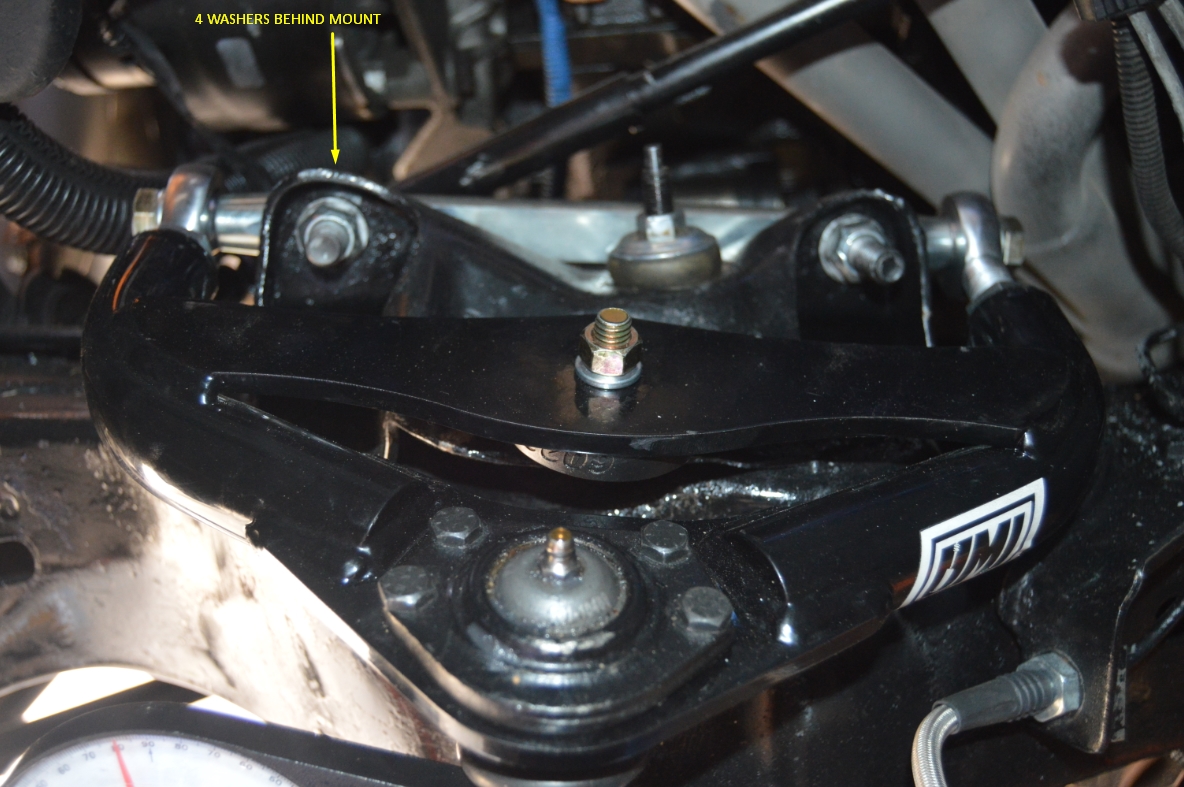
That means we need to put some shims on the backside of the frame mount (for the arm bolt), between that and the cross shaft of the arm.
(we thought having these cool basically “no-shim” arms would eliminate the need for shims entirely, but it turns out a few are needed to get the correct alignment we are seeking. oh well.)
We don’t have any wheel alignment shims laying around, but we do have heavy duty hardened washers, so that’s what we’re using.
(and they’re probably better anyways since there’s no chance of them coming out since wheel alignment shims are “U” shaped)
We screwed back in the rear bolt all the way, then adjusted the front bolt with the washers.
With 1 washer in place, it’s down to 7.5 degrees of positive caster (it started at 8 degrees before adjustments).
Thinking 1 washer = .5 degrees, we put a total of 6 washers in there.
Too much. We removed 2 of them, and success.
4 washers was the appropriate amount of spacers to get it to 5.0 degrees of caster.
.
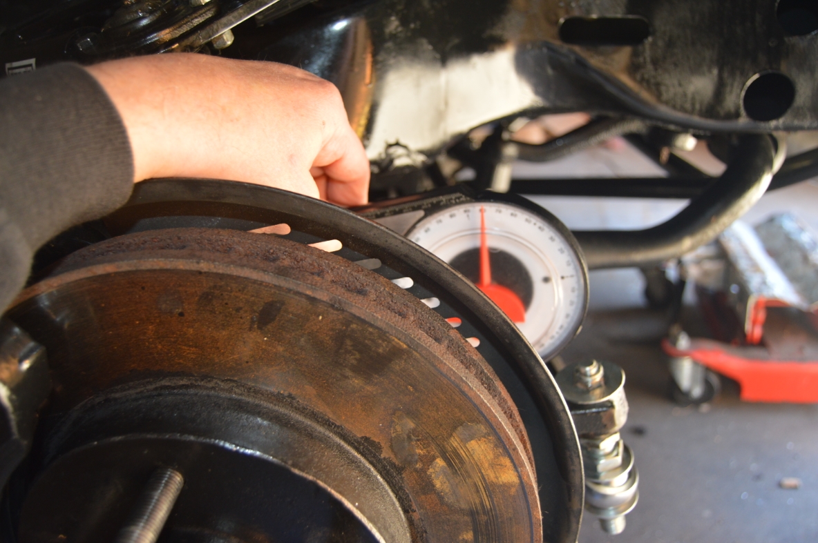
DRIVER SIDE:
.
![]()
.
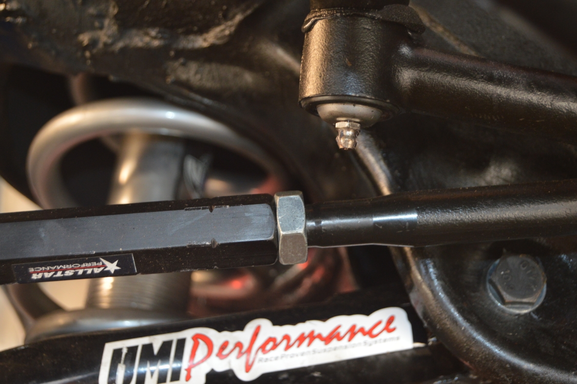
We used a floor jack to support the suspension (and lift it up) while we disconnected the cross shaft bolt.
(it’s a must, since otherwise you can’t lift the upper a-arm with a load on it)
There’s a lot of up/down action with the floor jack.
Up/down to maneuver the arm back in place or remove bolts, and up/down to put the suspension in the proper place (ride height) to measure.
.
[ just FYI, when we finally got the caster set to where we wanted: at ride height, passenger side was 5.5 degrees, at full droop it was 5.0 degrees, so there’s not a huge difference, but there IS half a degree, which could possibly affect the settings you want depending on where you set yours at. The drivers side measured the same way in difference between ride height vs full droop. Remember, you’re suppose to set caster at ride height.]
So, now that the caster adjustment is completed, we go back & check the camber for both sides.
The driver side was good (at 0).
The passenger side now measures -1 degree.
We included how we adjusted and fixed this above – under “just fyi” on the camber notes.
Both sides now measure 0 degrees of camber after another adjustment.
.
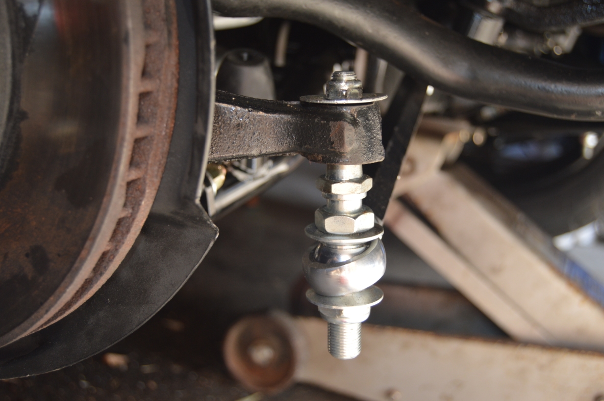
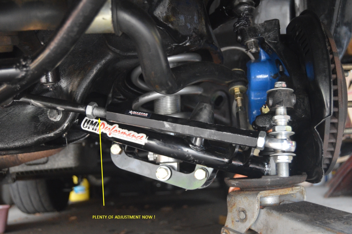
ADJUSTING TOE:
There is a bump steer kit on this Buick Regal GN, so adjusting toe is performed by turning the main center link on that kit.
If you have a stock steering system, you will need to loosen the 2 nuts holding the adjuster on, and spin that (in or out) until you get the needed setting.
(from the outside of the car, standing by the wheel, looking towards the center, spinning the adjuster counter-clockwise makes the tie rod overall length shorter, bringing the “toe” in. clockwise brings the toe out. The toe is the which way the front side of the tire points, in or out.)
(note that most of the adjusting, on this kit, will be done on the inner tie rod end. The inner has more threads than the outer tie rod end, so keep that in mind when reassembling the bumpsteer kit and reinstalling on the car. You want their to be more movement – in/out, to happen on the inner tie rod end, the outer end should be screwed in almost all the way in as possible)
It may be easier to check and adjust toe with the wheels on, depending on how you choose to do this.
Make sure your steering wheel is straight before you begin.
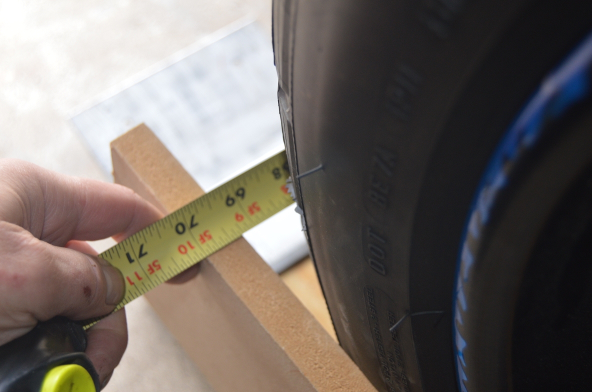
We used the same method as the guy did in the video, we strapped a board on the outside of the tires, and measured the distance between the front and the back sides.
We could visually see that both wheels needed to come in before we even measured, so we figured to bring the toe in by eye getting it close to straight.
The passenger side was done first.
We spun the bump steer kits center link in as far we could (butt up against both jam nuts), and looked at how the wheel was pointed.
It’s still very far off.
Removing the inner jam nut completely and turning the center link in as far as it would go, which was about 1/4″ from the ends of the thread on the inner tie rod before we couldn’t turn it any further, left the outer tie rod with about 1/4″ of exposed thread (plus the threads under the jam nut).
Again, looking at the wheel visually, it still needs to go in somewhere 1/4″ to 1/2 more.
Uggg.
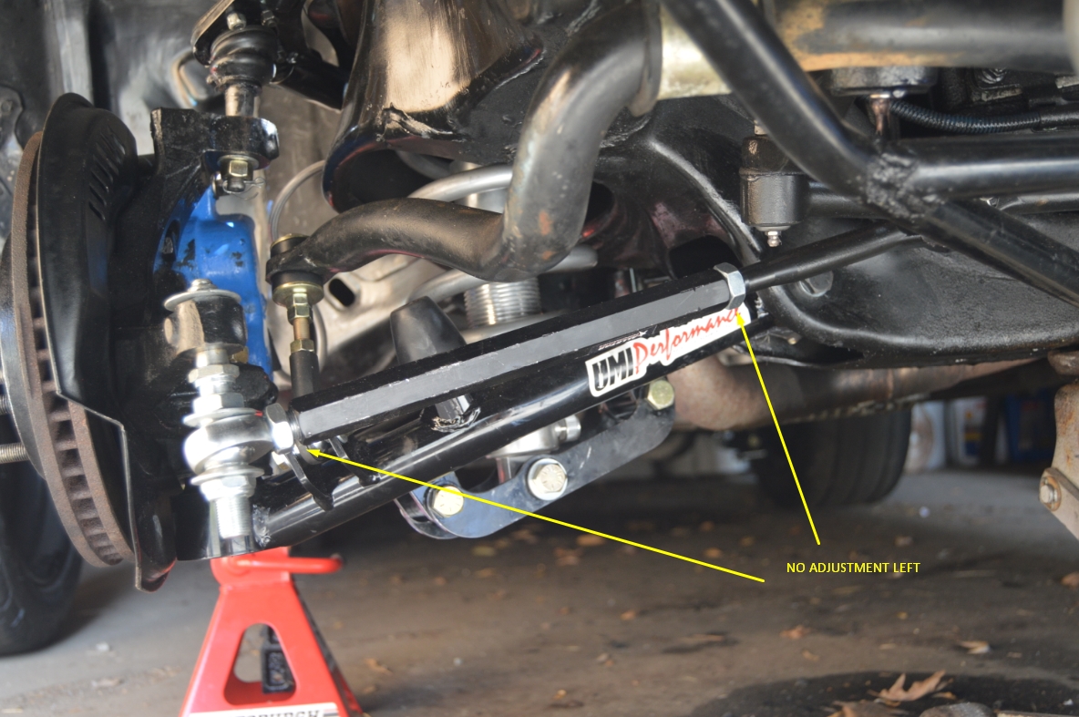
We’re out of adjustment.
.
.
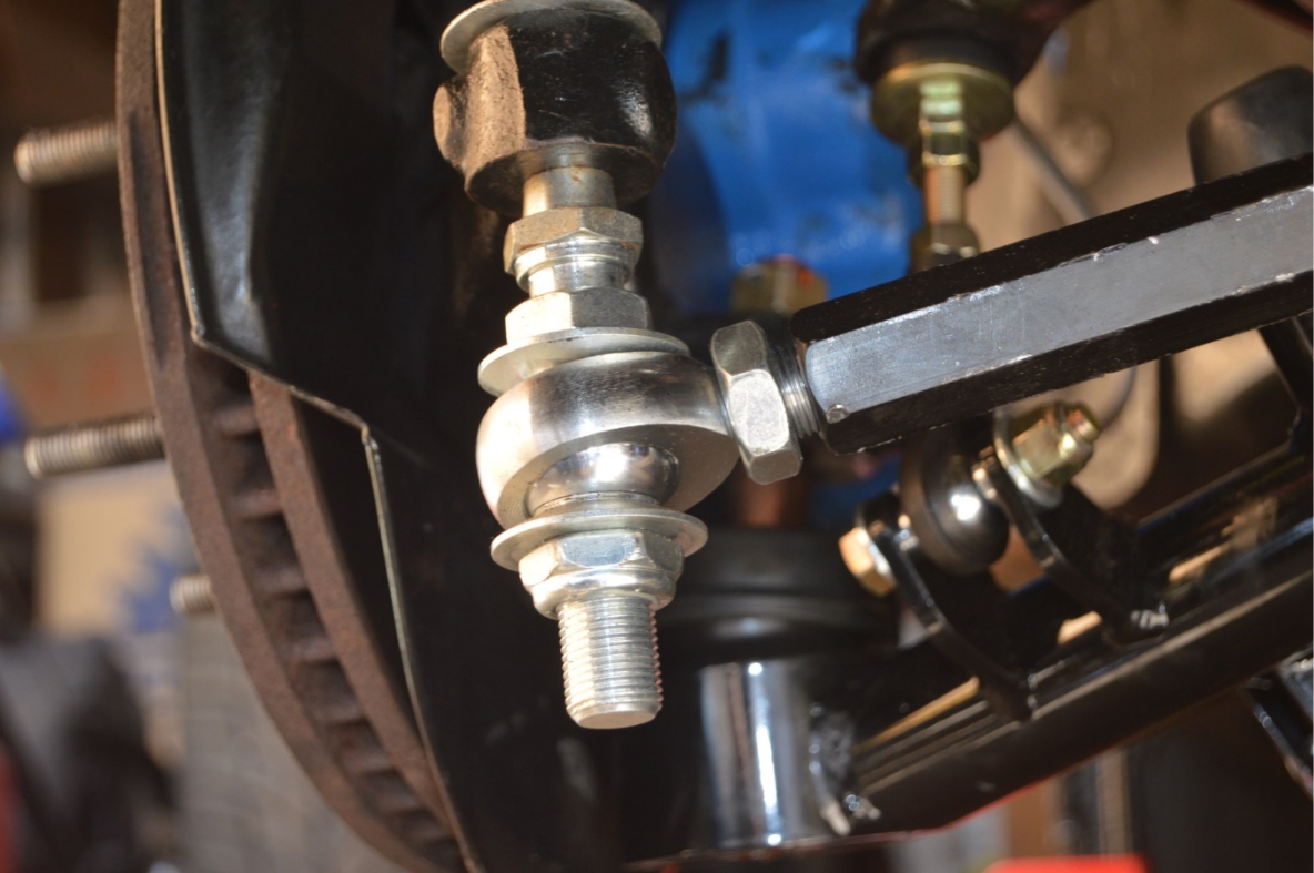
(note: removing the inner jam nut requires that the outer tie rod be disconnected from the spindle, so you can remove all the parts before that nut. Good thing since these are relatively new parts as it didn’t require too much effort using a pickle fork for removal)
Time to mess with the drivers side now to see what will happen on that side.
We put the inner jam nut all the way in (towards the inner tie rod) and spun the center link in as far as it would go (which would only go in as far as leaving it about 1/4″ from that jam nut, same as the other side did).
The outer tie rod end was put back on right up against the center link.
This pretty much leaves us with no more room for any more adjustment on either side.
The visual wheel check revealed a toe out condition again (but not as bad as before).
It’s getting there.
Now that (we think) we’ve gotten it close by eye, time to do the actual measuring part and see exactly where we’re at.
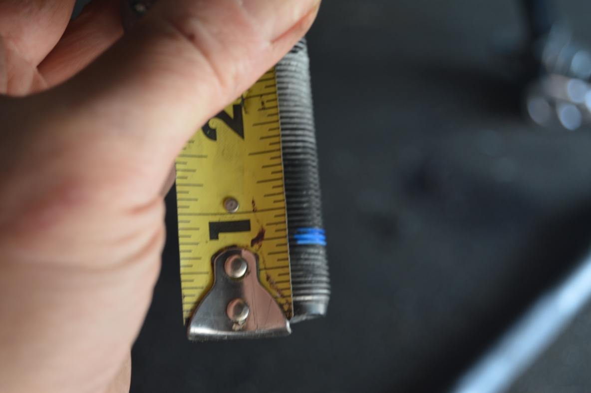
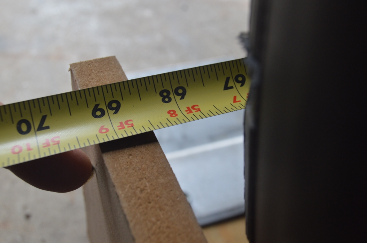
The front side measures 69.25″ and the back side measures 68.25″!
Our current toe is an inch off!
The toe right now is 1″ OUT.
The specs should say it need to be IN 1/16″.
So we need to bring in the toe by almost 1 inch.
(meaning make the tie rod length needs to be shorter than they are now)
This means each side has to come in about 1/2″.
.

.
(however, as visually the passenger side looks more “straight” than the drivers side does, we will attempt to bring the drivers side in more than the passenger side. So, like 3/4″ in on the driver side, and 1/4″ on the passenger, equaling the 1″ it needs to come in overall, roughly. That’s just so we can keep things mostly balanced on both sides, adjustment-wise.)
Only problem is, we have run out of adjustment room on the entire tie rod assembly!
Double uggg!
We’ve been messing with this for an hour and a half now, it’s time to stop and do some research and try to figure out HOW we’re going to make the tie rod lengths shorter.
Possibly cut the aluminum bump steer kits center link to make it shorter, giving us more room to be able to pull in both outer tie rods.
Our garage is now closed until tomorrow, so we can finish figuring out possible solutions tonight.
(But by the magic of the internet, there’s no waiting for you, you can see the conclusion below! But for us, we’ll have to wait an actual day, lol)
.
OK, TADA! We’re back!
After spending over an hour online reading assorted articles, forums, and installation instructions (from several different manufacturers of different “bump steer kits”) about installing a bump steer kit, there was plenty of details about the up/down adjusting of them (spacers and such), but only ONE that specifically mentioned about the center link being too long! (thanks “chassisworks” for the info!)
They said that you may have to either shorten the factory inner tie rod or the adjusting sleeve to correctly align the vehicle.
(or actually both in our case, since the center links are only threaded on the inside 2.25″ from the ends, and we intend to cut off 1″ of that, leaving us 1.25″ of thread. The center link threads will bottom out before it pulls in the wheels, hence the need to cut down the threads on the inner tie rod as well)
(There’s a lot of info online about the “theory” of bump steer, what it is, how/why you are suppose to adjust – using a bumpsteer gauge that almost no one has, but not a lot of practical information that would help the average Joe figure it out without taking it into a professional shop. There’s enough info about this to give you a headache if you read it all, and then you still won’t be able to set yours the right way, lol. Basically, make the tie rod assembly parallel to the lower a arm and that should be close enough, at least as a starting point)
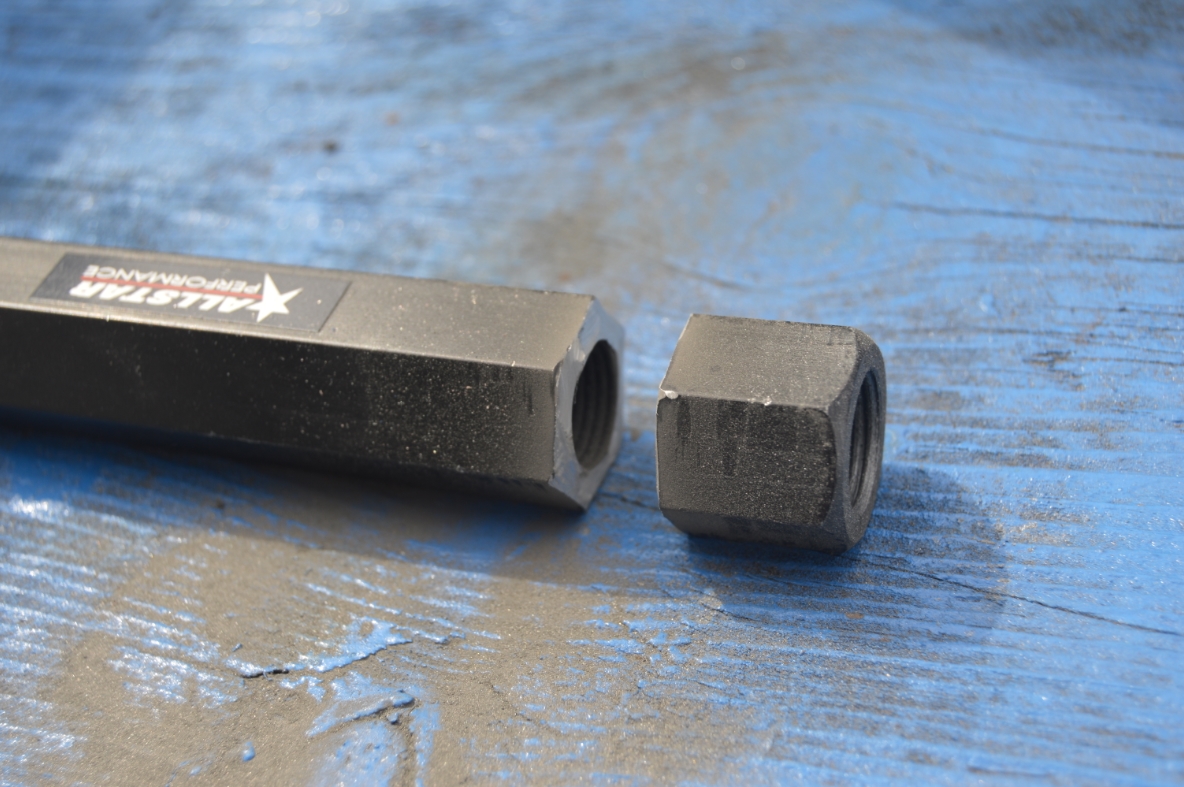
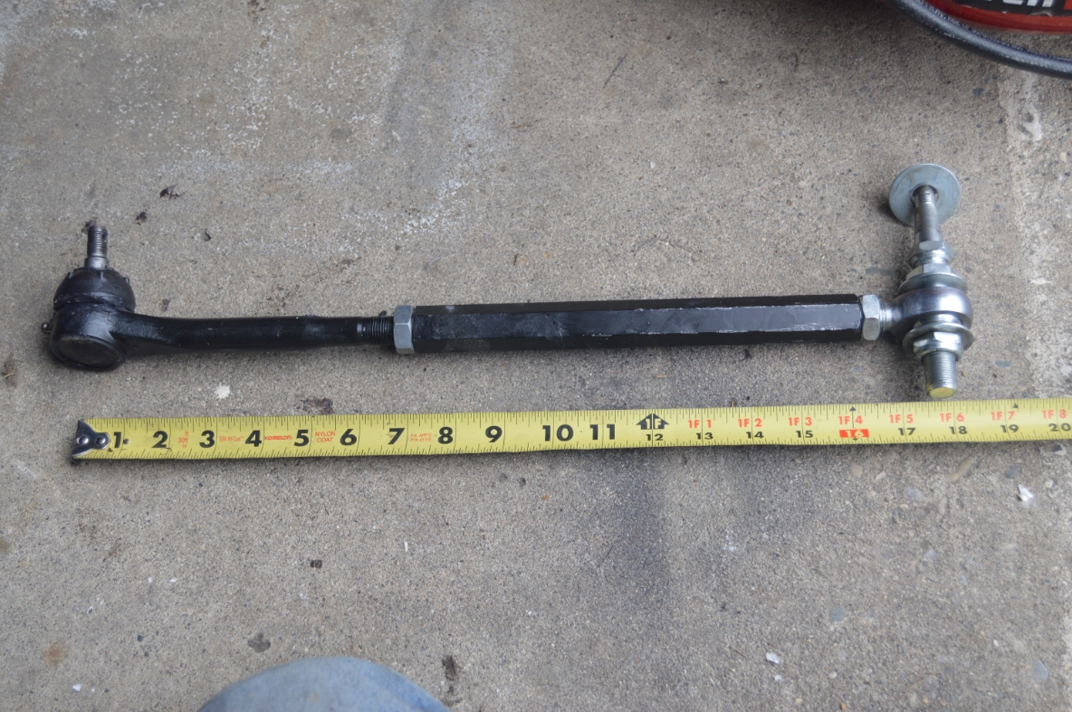
Since the sleeve we have is really long, trimming that piece down seems the best option.
(so our guess from yesterday about having to do this very thing, was correct!)
.
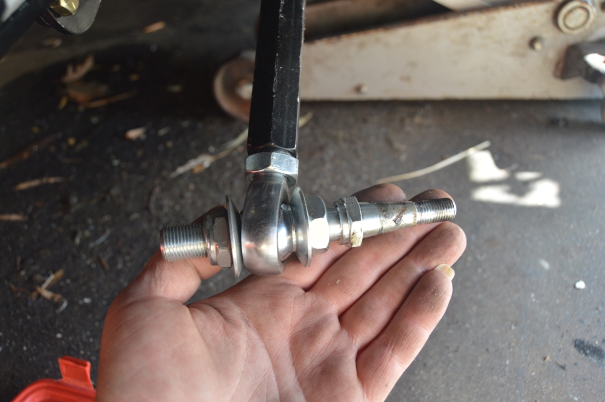
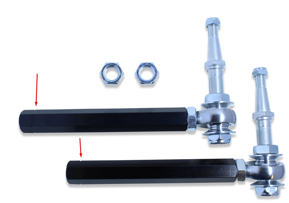
REMOVING OUTER TIE ROD & CENTER LINK:
.
.
The instructions for our specific G-body bump steer kit mentioned nothing about the length issue we’re having.
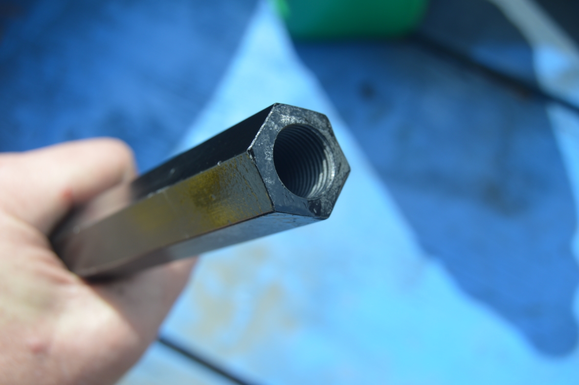
Looking at the actual sleeve however, we notice that on both pieces (both sleeves), they have an indented line on them about 1″ from the inside ends. That looks like it might be the place to shorten the sleeve at (might even be a factory mark for shortening them even though it didn’t say that anywhere).
The threads on the inside are still long enough to be usable after cutting.
(The side of the sleeve with the mark has threads that are about 2.25″ deep. The other end threads are only 1.25″ deep, on the inside of the tube)
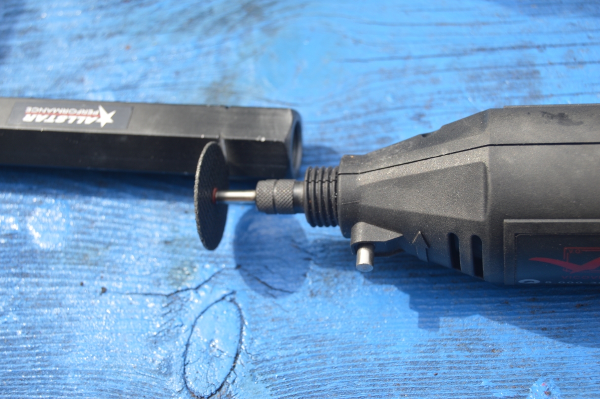
Pulling out our handy dandy dremel, we’re going to attack the adjuster sleeves.
Of course, that means popping off the outer tie rod end, and unscrewing the sleeve from the inner tie rod end.
.
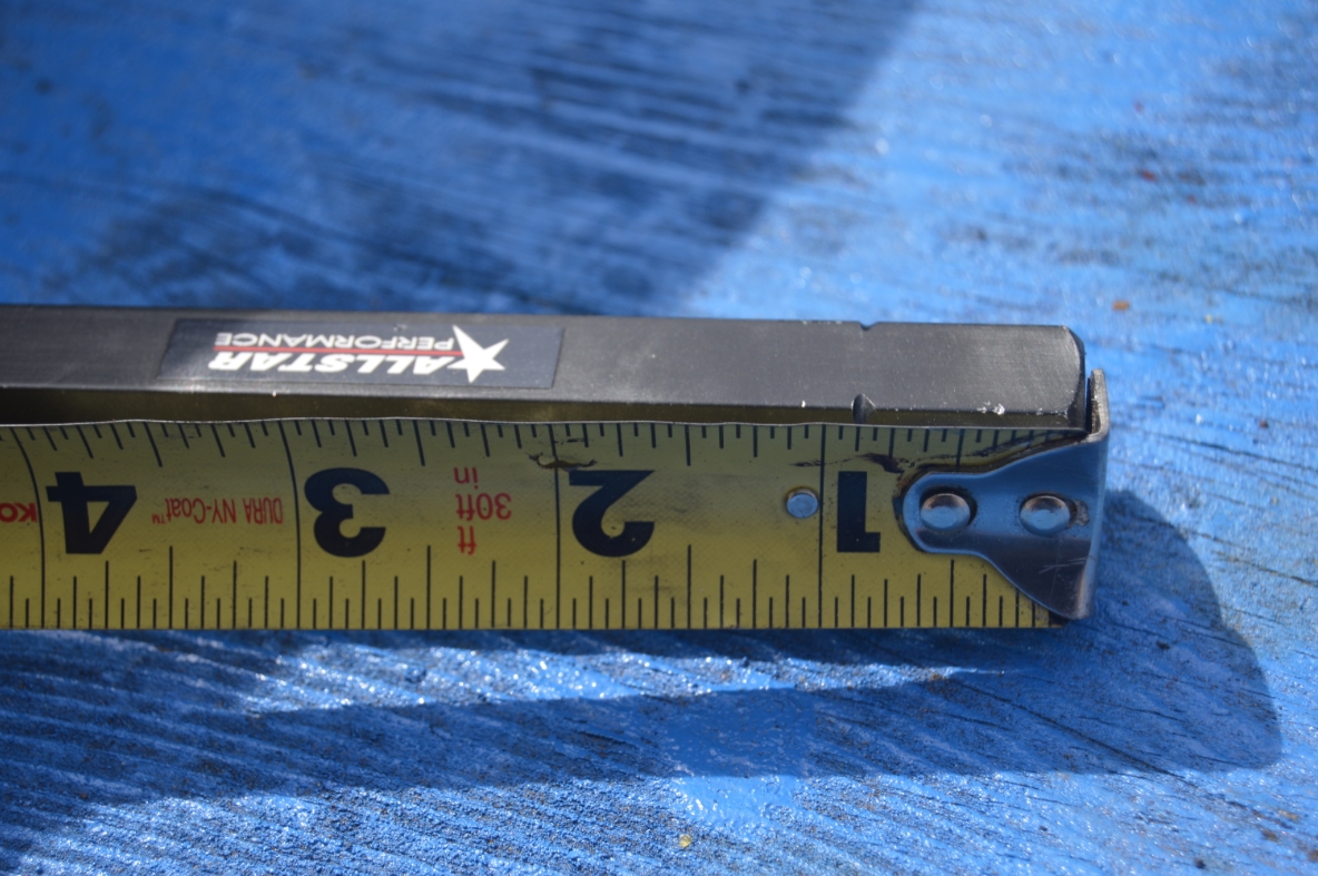
CUTTING THE CENTER LINK:
.
.
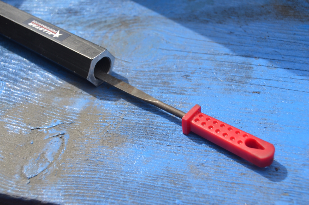
After cutting them down, they should short enough to be able to pull in the outer ends enough to achieve the proper toe in specs we need.
The inner toe rod ends also need to be trimmed down as well, as doing just the adjusters alone won’t fully accomplish this (since we had already bottomed out both sides). We cut off 3/4″ off of the both inner toe rods.
We filed down the edges of the cut section on the center link, and the tie rod.
We splashed a bit of black paint on the center section end we cut.
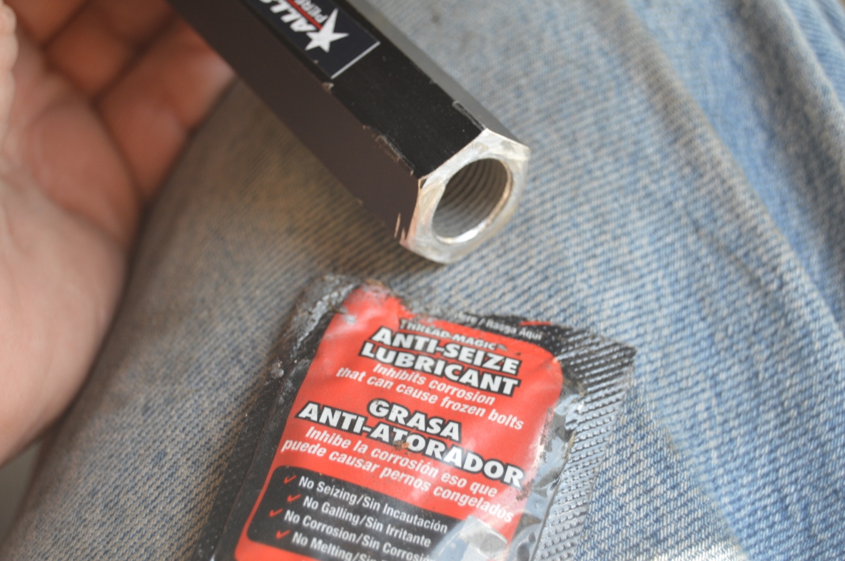
We slathered the sleeve threads with a dose of anti seize.
Reattaching the entire assembly, we can now begin (again) to reset the toe.
.
CUTTING THE INNER TIE ROD (done with it still installed on car):
.

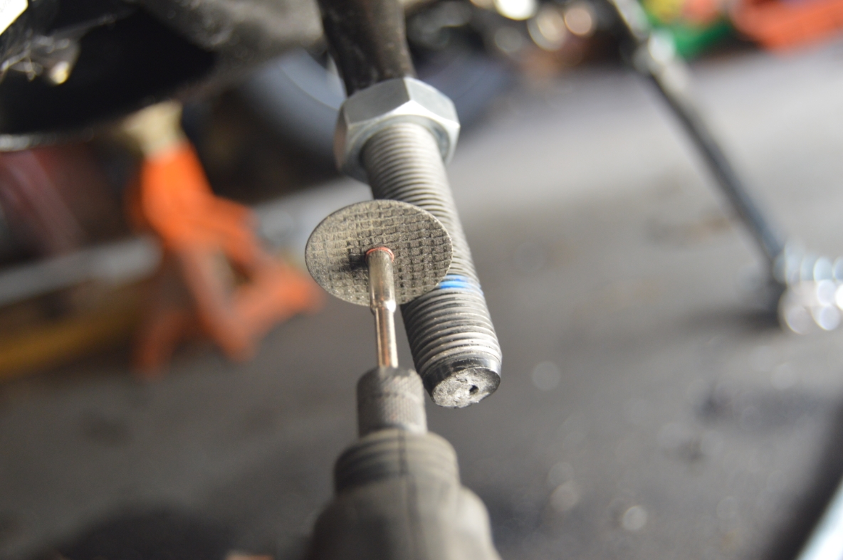

.
REINSTALLING THE TIE ROD / BUMPSTEER ASSEMBLY:
.

.
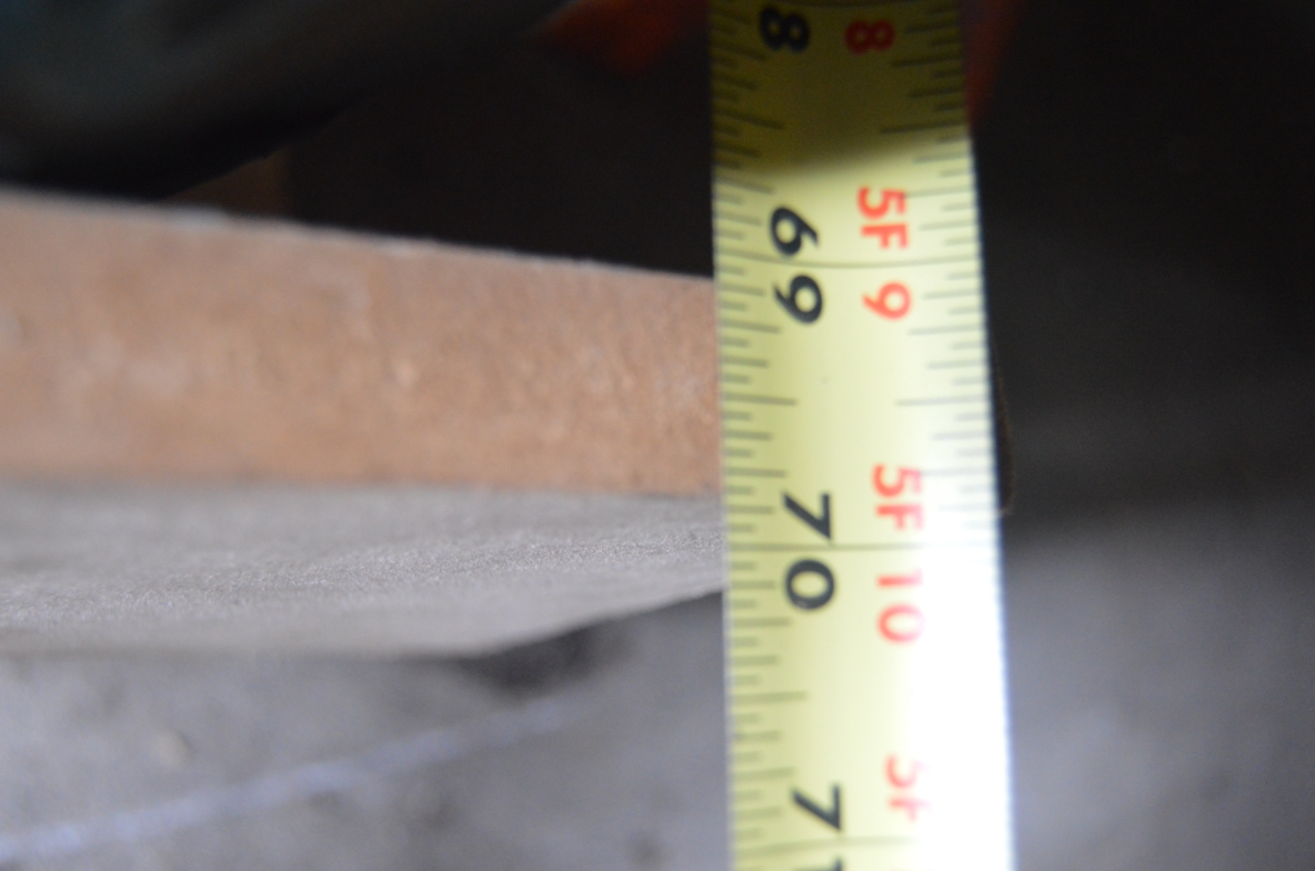
We made the driver side visually looking “straight” before the initial (re)measuring.
Our new toe numbers say:
front side = 68 1/2″
back side = 69 1/16″
.
.
Much better!
There’s a difference of 9/16″ between front and back, so bringing each front side out 1/4″ will give us our desired overall IN 1/16″ spec.
We adjusted them, and the front end alignment is done!
(68 3/4″ on the front, 68 13/16″ on the rear side of tire)
.
.
Now that all the adjusting is finally done, what a job this was! 🙁
Our ’87 Buick GN is ready to rock though!
Thanks for following along.
[ although this was a “fun” job to do, if I could go back in time, I’d take it into an alignment shop! You’d have to find a specialty professional though, the newer shops don’t really know how to do old school vehicles with aftermarket parts! ]
.