


This category on the website [ ECM Wiring Harness Related ] we are giving you all of the information related to the individual parts in the Buick Turbo Regal, along with the associated wiring, connector plugs, etc.
.
VEHICLE APPLICATION:
Buick Regal, T-Type, Turbo T, Limited, Grand National, GNX
PART NAME:
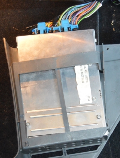
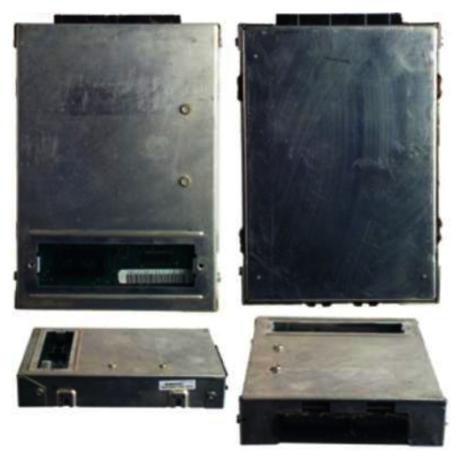
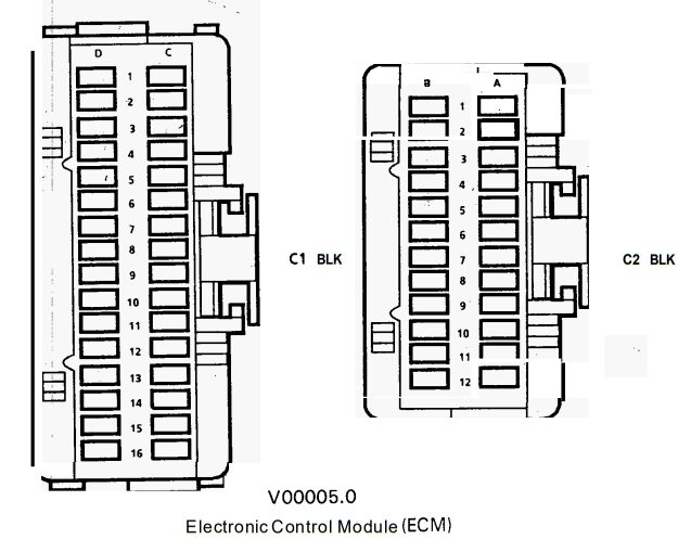
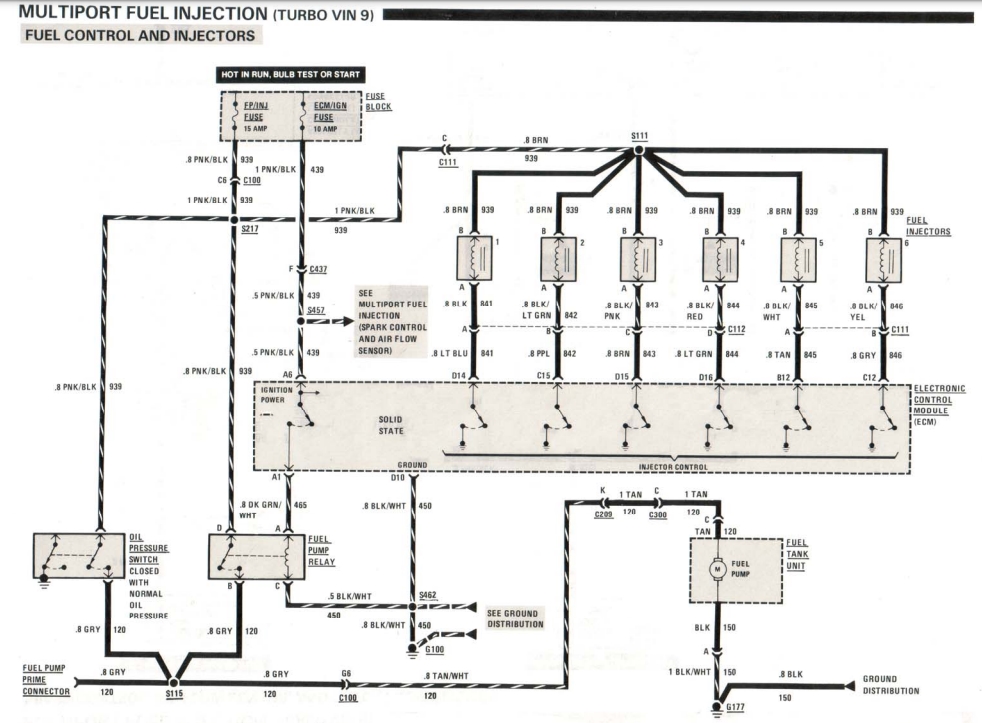
Electronic Control Module (ECM)
(vehicle computer)
PURPOSE OF PART:
the ECM runs the engine functions, as well as most of the other electrical components in the vehicle
TURNS ON-OFF / FUNCTIONS / USED WHEN:
constantly operating when the ignition key is forward/backward (in any position)
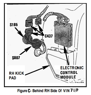
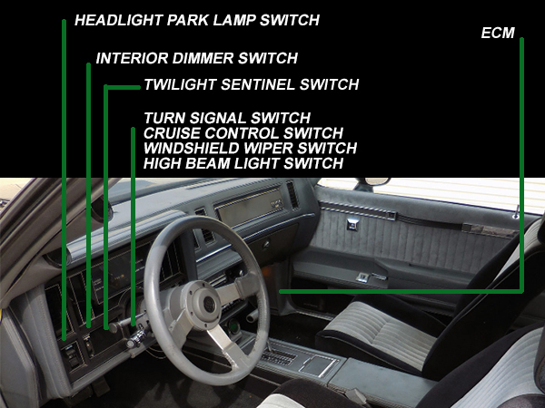
LOCATION IN VEHICLE:
interior compartment, RH (passenger) side, inside kick panel (near floor)
ORIGINAL GM PART NUMBER:
1227148
PART BASE COLOR:
metal case
CONNECTOR PLUG COLOR (PART SIDE):
black
WIRES ATTACHED (PART SIDE):
n/a
(no external wires)
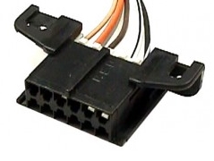
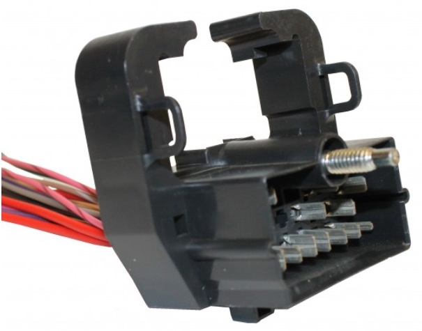
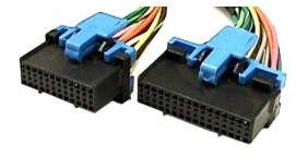
CONNECTOR PLUG COLOR (HARNESS SIDE):
black with blue clips
NUMBER OF WIRES ATTACHED (HARNESS SIDE):
45
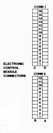
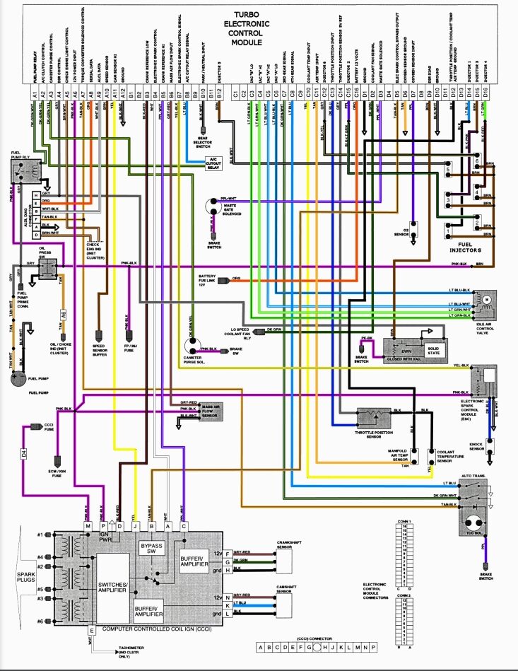
COLOR & PURPOSE OF (HARNESS SIDE) WIRES:
A1 dark green-white (ignition power), goes to fuel pump relay “D”
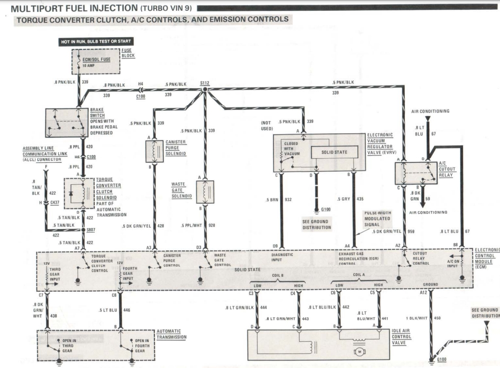
A2 dark green-yellow (cutout relay control), goes to a/c cutout relay “C” [clutch control]
A3 dark green-yellow (canister purge control), goes to canister purge solenoid “B”
A4 gray (exhaust gas recirculation (EGR) control), goes to EVRV “B” (via junction, with ALDL)
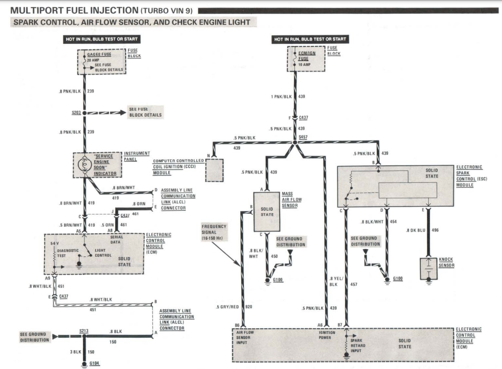
A5 brown-white (SES light control), goes to SES dash light [check engine light]
A6 pink-black (ignition power), goes to ECM/IGN fuse (via junction, with other things)
A7 tan-black (transmission converter clutch control), goes to TCC solenoid “D” (via junction, with ALDL)
A8 orange (serial data), goes to ALDL
A9 white-black (5v diagnostic test), goes to ALDL
A10 brown (vss input), goes to VSS buffer “A” (and junction that conencts to I/P digital cluster)
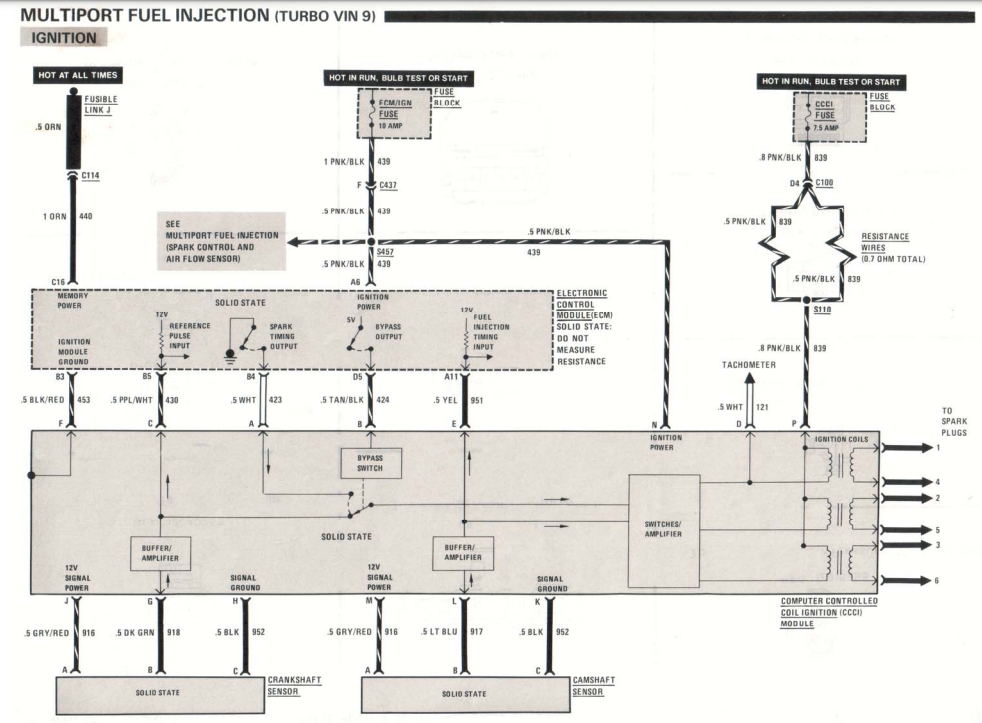
A11 yellow (fuel injection timing output), goes to ignition module “J” [cam sensor high]
A12 black-white (ground), goes to ground
B1 [ not used ]
B2 [ not used ]
B3 black-red (ignition module ground), goes to ignition module “D” [crank ref low]
B4, white (spark timing output), goes to ignition module “A” [electronic spark control]
B5 purple-white (12v ref pulse input), goes to ignition module “C” [crank ref high]
B6 gray-red (air flow sensor input), goes to mass air flow sensor “B” [mass air flow input]
B7 yellow-black (spark retard input), goes to ESC Module “C” [electronic spark control signal]
B8 light blue (a/c on input), goes to a/c cutout relay “B” [a/c cutout relay signal]
B9 [ not used ]
B10 orange-black (park/neutral input), goes to gear selector switch “B” [park/neutral input]
B11 [ not used ]
B12 tan (fuel injector control), goes to fuel injector “A” (black-white wire) [injector 5]
C1 [ not used ]
C2 [ not used ]
C3 light green-black (coil B low), goes to idle air control valve [IAC B low]
C4 light green-white (coil B high), goes to idle air control valve [IAC B high]
C5 light blue-white (coil A high), goes to idle air control valve [IAC A high]
C6 light blue-black (coil A low), goes to idle air control valve [IAC A low]
C7 dark green-white (third gear input), goes to automatic transmission “C” (third gear) [3rd gear signal]
C8 light blue (fourth gear input), goes to automatic transmission “B” (fourth gear) [4th gear signal]
C9 [ not used ]
C10 yellow (coolant temperature input), goes to coolant temperature sensor “B”
C11 tan (manifold air temp input), goes to manifold air temperature sensor (IAT) “B”
C12 gray (fuel injector control), goes to fuel injector “A” (black-yellow wire) [injector 6]
C13 dark blue (throttle position input), goes to TPS “B”
C14 gray (5v ref power, supply), goes to TPS “A”
C15 purple (fuel injector control), goes to fuel injector “A” (black-light green wire) [injector 2]
C16 orange (memory power), goes to fusible link “J” (connects at battery; constant hot wire) [battery 12 volts]
D1 black-white (power ground), goes to ground (junction)
D2 dark green (coolant fan signal), goes to low speed coolant fan relay “?”
D3 purple-white (waste gate control), goes to waste gate solenoid “A”
D4 [ not used ]
D5 tan-black (ignition power 5v bypass output), goes to ignition module “B” [electronic spark control bypass output]
D6 tan (oxygen sensor ground), goes to ground (junction)
D7 purple (oxygen sensor input), goes to oxygen sensor
D8 [ not used ]
D9 brown (diagnostic input), goes to EVRV “C” [EGR diagnosis]
D10 black-white (ground), goes to ground (via junction, with other things)
D11 [ not used ]
D12 black (5v ref power, return), goes to (junction, with other things) [TPS, coolant temp, air temp ground]
D13 [ not used ]
D14 light blue (fuel injector control), goes to fuel injector “A” (black wire) [injector 1]
D15 brown (fuel injector control), goes to fuel injector “A” (black-pink wire) [injector 3]
D16 light green (fuel injector control), goes to fuel injector “A” (black-red wire) [injector 4]
.
OTHER NOTES:
Small connector is 24 cavity (wires), larger one is 32 cavity (wires).
Most remanufactured units do not include any chips.
There are 2 chips that run the engine & other systems:
Prom chip: this is the main chip
Calpak: this is the “limp home” (emergency) chip (makes the car minimally operable but runs).
[there’s many aftermarket chips available, turbo tweak, speed density type chips, bailey chips: commander, extender]
Some owners have upgraded (removed) the stock ECM unit with newer technology.
Popular stand alone ecm/ecu/pcm/engine management computer system upgrades include:
ECU-GN
Fast XFI
MegaSquirtPNP / MS3Pro
Holley EFI
.
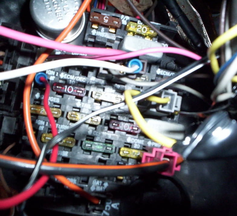
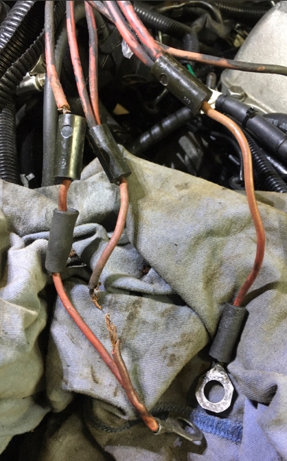
PHOTOS OF PART AND CONNECTED WIRES:
.

.
.
Here’s a list of all of the ECM Wiring Harness Starting Charging Ignition Wiring & Connectors in the Buick Regal:
(click the links to go to the one you need info about)
* ALDL
* Alternator
* Battery Cables (Positive & Negative)
* Bulkhead Connections & Distribution Blocks
* Coil Pack
* ECM Memory Power Wire
* ECM
* Fuel Pump Test Tap
* Fuse Box
* Fusible Links
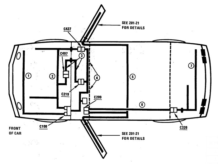
* Harness Routing
* Ignition Module (IM)
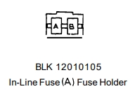
* Inline Fuses
* Main Grounds (Grounding Points)
* SES Light
* Starter
* Tach Tap Harness
* Volts Light
* Wiring Harness (Main Harnesses in car)
.