This category on the website [ Starting Charging Ignition Wiring & Connectors ] we are giving you all of the information related to the individual parts in the Buick Turbo Regal, along with the associated wiring, connector plugs, etc.
.
VEHICLE APPLICATION:
Buick Regal, T-Type, Turbo T, Limited, Grand National, GNX
PART NAME:
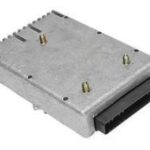
Ignition Module
PURPOSE OF PART:
controls coil pack, receives signals from cam & crank sensors, sends info to ECM
TURNS ON-OFF / FUNCTIONS / USED WHEN:
in constant use when the engine is running
LOCATION IN VEHICLE:
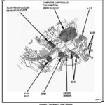
engine compartment, center rear, top of motor in back, under coil pack
ORIGINAL GM PART NUMBER:
25526449
ACDelco 24503624
19260720
PART BASE COLOR:
metal
CONNECTOR PLUG COLOR (PART SIDE):
black
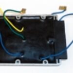
WIRES ATTACHED (PART SIDE):
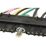
4 connector wires between ignition module and coil pack.
left to right: yellow, green, blue, dark blue.
CONNECTOR PLUG COLOR (HARNESS SIDE):
black
NUMBER OF WIRES ATTACHED (HARNESS SIDE):
14
COLOR & PURPOSE OF (HARNESS SIDE) WIRES:
14 connector wires on the ignition module.
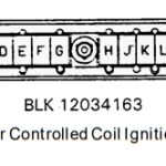
They are labelled (on the connector) as A thru P (with no letter “I” or “O”).
A-G on 1 side, H-P on the other.
The screw that holds the connector to the IM divides these.
label – color wire – goes where:
a= white wire, EST, goes to ECM (B4) spark timing output
b= tan-black, bypass, goes to ECM (D5) ignition power bypass output
c= purple-white, ref high, goes to ECM (B5) 12v ref pulse input
d= black-red, ref low ground, goes to ECM (B3) ignition module ground
e= white-tan, tach, goes to tachometer
f= gray-red, crank signal ground, goes to crankshaft sensor “C”
g= black, crank sensor buffer/amp, goes to crankshaft sensor “B”
h= dark green, 12v crank signal power, goes to crankshaft sensor “A”
j= yellow, cam signal for sfi, goes to ECM (A11) fuel injection timing input
k= light blue, cam signal buffer/amp, goes to camshaft sensor “B”
l= black, cam sensor ground, goes to camshaft sensor “C”
m= pink-black, goes to (junction) to CCCI Fuse
n= gray-red, cam sensor 12v signal power, goes to camshaft sensor “A”
p= pink-black, ecm fuse, goes to ECM/IGN fuse (junction, with other things)
.
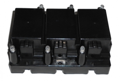
PHOTOS OF PART AND CONNECTED WIRES:
.
.
OTHER NOTES:
[SEE coil pack]
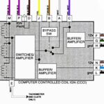
This is part of the CCCI (Computer Controlled Coil Ignition, or “C3I”) system.
[the Coil Pack is the other part of this setup]
[see the “Coil Pack” page for details about that section]
Coil Pack/Ignition Module replacement requires a new gasket every time either of these are done.
C3I module connector (IM module connector) on the 1986/1987 is different than 1984/1985
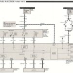
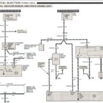
wiring diagram of how the coil pack & ignition module gets wired up:
ccci ignition wiring
For better performance, we created our own ignition module hotwire kit
.
Here’s a list of all of the ECM Wiring Harness Starting Charging Ignition Wiring & Connectors in the Buick Regal:
(click the links to go to the one you need info about)
* ALDL
* Alternator
* Battery Cables (Positive & Negative)
* Bulkhead Connections & Distribution Blocks
* Coil Pack
* ECM Memory Power Wire
* ECM
* Fuel Pump Test Tap
* Fuse Box
* Fusible Links
* Harness Routing
* Ignition Module (IM)
* Inline Fuses
* Main Grounds (Grounding Points)
* SES Light
* Starter
* Tach Tap Harness
* Volts Light
* Wiring Harness (Main Harnesses in car)
.


